« 1 2» Pages: ( 1/2 total )
本页主题: 【挖坑翻译】T-34/76 苏联红军战术手册 苏联国防人民委员会颁发1942 莫斯科 打印 | 加为IE收藏 | 复制链接 | 收藏主题 | 上一主题 | 下一主题

vonreynard
匈牙利人民共和国国民议会主席团主席
第一次社会主义劳动英雄称号 十月革命勋章 第一枚劳动红旗勋章
级别: 贵宾/顾问/元老


精华: 2
发帖: 1011
爱心: 1011 点
金钱: 10400 卢布
好评度: 0 点
国籍门派: 匈牙利人民共和国
在线时间:649(小时)
注册时间:2007-11-23
最后登录:2011-07-21

 【挖坑翻译】T-34/76 苏联红军战术手册 苏联国防人民委员会颁发1942 莫斯科

0
管理提醒:
本帖被 红军战神 从 军事百科 移动到本区(2015-11-07)
/hWd/H]  
THE DIRECTORATE OF THE ARMOURED FORCES OF THE RED ARMY 66&EBX}  
For Service Use.
<Q <AwP  
T-34 TANK ]:]H:U]p  
SERVICE MANUAL
IV16d  
People's Commissariat of Defence -F/st  
of the U. S. S. R. %hS|68pN6  
Moscow 1942
+ZsX*/TOn  
B0}~G(t(  
封面 Y qdWctUY  
-!M,75nU  
此文俄文到英文的翻译由比利时的modea van Saeuqiua完成,首先在此对其辛勤工作表示感谢 F4#g?R ::U  
AIl4]F5I  
此文有助于了解罗刹国的坦克设计思路和基本性能,尤其对装甲武器专业的武器设计有较大帮助 's?Ai2=#  
[ 此帖被vonreynard在2008-09-09 12:25重新编辑 ]
享生一世澜陨阔
斯年寸草何足灼
留待后世话今昔
烈风细雨笑声谈
顶端 Posted: 2008-09-09 12:13 | [楼 主]
vonreynard
匈牙利人民共和国国民议会主席团主席
第一次社会主义劳动英雄称号 十月革命勋章 第一枚劳动红旗勋章
级别: 贵宾/顾问/元老


精华: 2
发帖: 1011
爱心: 1011 点
金钱: 10400 卢布
好评度: 0 点
国籍门派: 匈牙利人民共和国
在线时间:649(小时)
注册时间:2007-11-23
最后登录:2011-07-21


%HQ.|  
$ZPX]2D4B#  
2s*#u<I  
=6FUNvP#8  
Chapter I. SHORT DESCRIPTION OF THE TANK
第一章       总览
The T-34 is a tracked fighting vehicle. The crew of tank consists of four men. The Tank is armed with a 76 mm. tank gun and two machine guns. The principle parts of the tank are: gV1[3dW  
1. Hull and turret j83? m  
2. Armament <HWS:'1  
3. Engine gIWrlIV{9  
4. Transmission 6Q4X 6U:WB  
5. Suspension $VG*q  
6. Equipment T[k4lM  
1:C:?ZC#c  
T-34 坦克是一个履带作战车辆,作战人员4人,武备76MM坦克炮,两个车载机枪,以下是坦克的主要部分 U;_[b"SW%  
1.装甲壳与炮塔 _s,ao '/  
2武器 wCMQPt)VS  
3.传动装置 %sh>;^58P  
4.悬挂装置 ukgAI<O%  
5.器材设备 Z!d7&T}  
_eSd nHWx  
The Hull ?B@;QjhjiJ  
The hull is divided into four compartments, driving, fighting, engine and transmission. ,?UM;^  
The driving compartment is situated in the front part of the tank; it contains the seats of the mechanic-driver and gunner-wireless operator, the driving controls, instruments, engine controls and electrical equipment, machine gun, part of the fighting equipment. wireless set (not in all tanks) , three periscopes, control for rear louvres, two compressed air bottles, spare parts, tools and ancillaries. q:>^ "P{  
The driver's hatch is in the glacis plate. In the floor at the feet of the gunner-wireless operator, there is an auxiliary escape hatch which is closed by an armoured door from within. The driver's hatch is fixed with hinges and has two locks which can be opened from within by pulling a strap which connects both locks. To assist opening the hatch a balancing mechanism (Plate I) is provided together with a catch and handwheel for supporting it in the open position. i[C~5}%  
5/",<1  
装甲壳体划分成四个部分,驾驶部分,作战部分,引擎与传动部分 3>ex5  
驾驶部分放置在坦克前部,有机械驾驶员座椅和无线电员兼炮手的操作位,驾驶控制装置,驾驶仪,引擎控制,电动装置,车前机枪,(部分战斗武器),无线电装备,(不是所有车都有)三个潜望镜和观察孔透镜,后部排烟装置(?)两个压缩空气瓶,备件箱,备用工具,  9DQ)cy  
驾驶员的舱口是个有斜度的装甲板,在板一侧是无线电员兼炮手的操作位,这个也是一个辅助的逃逸出口,一般被里面的装甲门从内部关住,驾驶员舱是被铰链固定,两边各有两个扣子,这玩意儿可以用个皮带拉开,可以通过平衡机械装置拉开这个装置于驾驶盘上(见板图1), 1L7{p>;-dO  
  -!RtH |P  
2 gq$C"  
Plate 1 - Balancing mechanism of the driver's hatch J;t 7&Zpe  
1. Hand lever Gz I~TWc+G  
2. Body ivO/;)=t  
3. Plate )/ Ud^wi  
4. Spring VO3pm6r5  
5. Centralising bush 9CGNn+~YI  
6. Spring d|9b~_::V  
7. Rear flange E! /[gZ  
8. Rod JE 5  
9. Pivot rjt8fN  
10. Lock $lIWd  
11. Handwheel RhI;;Y#@  
H?1xjY9sl  
例图1-驾驶员舱口盖的平衡机构 B@Co'DV[/]  
1手柄  v7  
2主转钮 _3iHkQr  
3.盖板 I-D^>\k+  
4弹簧 ubsSa}$q  
5.中央衬套 zo{/'BnU  
6.内弹簧 {3a&1'a0g  
7.后轮缘 I:&/`K4,x,  
8.按杆 %z]U LEYrZ  
9.轴枢纽 4nfu6Dq  
10.固锁装置 R9We/FhOY  
11.驾驶盘 +.B<Hd  
# m R4fst  
The fighting compartment is situated in the middle part of the tank. It contains the seats of' the tank commander and the turret gunner. The turret which rests on a ball race on top of the fighting compartment contains the 76 mm. tank gun and the ATmachine gun co-axially mounted, part of the fighting compartment and observation instruments. u*S=[dq  
Behind the removable plate of the partition are four fuel tanks - two at each side. In the middle and at the sides, part ,of the fighting equipment is kept. In the right hand corner there is an electric fan. On the roof of the fighting Compartment there arc six openings -three at each side. The central openings are used for filling up the tanks with fuel; and the remainder are for inspection, maintenance and lubrication of the suspension. In the floor of the fighting compartment there are three openings under the fuel tanks for draining off fuel ( the openings are closed by threaded plugs). There are also four slits for the removal and inspection of the suspension units. These are closed by caps on the outside of the tank. :pX`?Ew`g  
The Engine compartment is situated behind the fighting compartment and is separated from it by a dividing bulkhead (Plate 2). The following are installed in the engine compartment: the engine, two water cooling radiators, two oil tank , radiators, four accumulators. The floor of the engine compartment is fitted with an access door for the oil pump and water pump ( this is closed by an armoured cover on the outside of the vehicle), an aperture for draining water and three slits for the removal and inspection of the suspension (these slits are closed by means of armoured covers on the exterior of the vehicle). lLq<xf  
The engine compartment roof has a large hatch for access to the engine (this is closed by a cover and secured by a lock), two air louvers over the radiators. There are four access plates at each side; the central ones provide access to the filler plugs and oil tank cocks and the ones at each side are for access to the adjustment of the suspension. %A1@&xrbl  
C-eA8pYY/  
Plate 2 - Engine Bulkhead Mk 0+D#  
1. Hand lever for louvre control ))D:8l@  
2. Cover of the ventilating hatch \mM<\-'p  
3. Upper central removeable plate i=a-<A5x  
4. Threaded grease gun L(S'6z~_9  
5. Access door for fuse box =rA~7+}  
6. Access door for oil cock wCs^J48=  
7. Fuel distributor cock \b V6@#,  
8. Lower central removeable plate a/Q$cOs  
9. Nut of steem valve z@|dzvjl Q  
The transmission compartment is situated in the rear part of the tank; it contains the engine clutch with centrifugal ran, gearbox, steering clutches with brakes, electric starter, final drives with two fuel tanks. The floor of the transmission compartment is provided with two apertures at the side for draining fuel (these apertures are closed by threaded plugs on the outside) and one opening Jon thc middle under the gear box for draining off oil (this opening is closed by means of an armoured cover from the outside). Xm2\0=v5;  
In the roof of the transmission compartment, over the fan there are air inlet louvres (Plate 3). These are provided with a metal netting for keeping out foreign bodies. These are two access plates in the roof for the fuel tanks and filler plugs. n>3U_yt6b  
(;x3} ]  
Plate 3 - Air Louvre control linkage Kyt)2p  
1. Segment :%&Q-kk4!  
2. Hand lever with lock <`X"}I3 ba  
3. Eye mpC`Yk  
4. Lost motion device $\o {_?}1  
5. Tie-rod b2(RpY2Y  
6. Eye  @4d)R  
7. Tie-rod m~#!  
8. Lever wZT%Ee\D%  
9. Louvres W+wA_s2&D  
The Turret (Plate 4) UEs7''6RM  
In the front of thc turret in a mantlet are installed: the 76 mm. gun and the co-axially mounted ATmachine gun and the telescopic sight TMOA-7. At the left of the gun on the turret neck the turret traversing gear is fitted. ;DA8B'^>  
The rear plate of the turret is removable. Fixed to the sides of the turret are the observation instruments and underneath them a revolver port is provided which is closed by means of a conical plug. This plug is inserted from the outside and pushed open by a steel lever. The rear part of the turret roof is fitted with an access hatch on the top of which there is a signal port. Fitted on to the front part of the roof are the instruments NTK-5 and NT-7 and between them a hatch is provided for ventilation which is covered by an armoured cap. The turret is prevented from coming off by turret clips. In the rear clip is incorporated a travelling lock for the turret. 'mCe=Y  
+i ?S  
Plate 4 - Turret (front) YG:3Fhx0~  
Door in the Access hatch of the Turret A,-6|&F  
In the closed position, the door (Plate 5) is secured by a lock (Plate 6) which is opened from the outside by a key. To open the lock from within it is necessary to press the catch (# 7), turn the lever (# 6) perpendicularly to the surface of the roof and pull the lever (# 4). In the open position, the roof is supported by a pawl (# 2). To close the roof it is necessary to press the knob (# 5) and remove the pawl. To facilitate the opening and shutting of the roof a balance spring (Plate 5) is provided. ,&PE6h n  
[ 此帖被vonreynard在2008-09-09 15:25重新编辑 ]
享生一世澜陨阔
斯年寸草何足灼
留待后世话今昔
烈风细雨笑声谈
顶端 Posted: 2008-09-09 12:14 | 1 楼
vonreynard
匈牙利人民共和国国民议会主席团主席
第一次社会主义劳动英雄称号 十月革命勋章 第一枚劳动红旗勋章
级别: 贵宾/顾问/元老


精华: 2
发帖: 1011
爱心: 1011 点
金钱: 10400 卢布
好评度: 0 点
国籍门派: 匈牙利人民共和国
在线时间:649(小时)
注册时间:2007-11-23
最后登录:2011-07-21


Plate 5 - Turret Access Hatch "G >3QL+O|  
1. Hinge >+. ( r]  
2. Pawl T5urZq*R  
3. Bracket ]# t6Jwk  
4. Rubber pad T0)4v-EO  
5. Knob 3mPjpm  
6. Bracket fQrhsuCrC  
7. Lock y"]n:M:(  
8. Spring 'c\iK=fl  
9. Pivot Ehz o05/!  
10. Bracket YV=QF J'  
11. Casing ntNI]~z&  
12. Hinge pEECHk  
Plate 6 - Turret Hatch Lock *5bLe'^\|K  
1. Body =U|N=/y#hJ  
2. Supporting shaft r&-m=Kk$  
3. Vertical shaft <Q|d&vDVfV  
4. Lever '|;X0fD  
5. Stud ,mRyQS'F  
6. Hand lever R.7:3h  
7. Lock '=][J_  
Turret traversing Gear 7+./zN  
The traversing gear enables the turret to be rotated either by hand or by means of the (electric motor clockwise or anti-clockwise. The construction of the traversing gear is shown in Plate 7. Cg*H.f%Mr  
/iG*)6*^k  
Plate 6 - Turret Traversing Gear 3+ >G#W~  
1. Pinion Q1V9PRZX  
2. Cone friction clutch Y*_)h\f  
3. Shaft }@if6(0  
4. Planet carrier J0zn-  
5. Lower casing f7Ul(D:j\  
6. Upper casing &d7Z6P'`G  
7. Worm wheel for the hand wheel NM)k/?fA  
8. Satellite wheels :Xc@3gF  
9. Satellite pins ]weoTn:  
10. Pinion 3_JCU05H}  
11. Worm wheel for electric motor S"9zc ,]  
12. Worm hdTzCfeZ5@  
13. Worm for handwheel FP[!BUOf"  
14. Handwheel t|t#vcB  
15. Electric motor E .1J2Ne  
16. Driving pinion aq7~QX_0G  
17. Parasite pinion /0\ mx4u  
18. Driven pinion !w BJ,&E  
19. Rubber ring `1:{0p2q  
20. Electric motor handwheel stop knob #plY\0E@  
21. Nut retaining the bodies (EPsTox  
22. Packing disc for the lower casing $mF_,|  
23. Disc with worm wheel lKk/p^:  
24. Cover j }b\Z9)!  
25. Electric motor control handwheel ? ` SUQm  
To turn the turret by hand it is necessary to rotate the handwheel (# 14), in the direction required. To use the electric motor it is necessary to press knob (# 20) of the catch and turn the handwheel in the direction required. When the handwheel is in the neutral position, the catch returns automatically. The clutch spring of the gear (# 1), when in the fully compressed position, should measure 32-35.5 mm. long. a>\vUv*  
Ammunition Stowage `y#UJYXQE  
The ammunition is partly stowed in the fighting compartment and in the bulkhead partitions and partly in special boxes. There are six boxes of 9 rounds and two boxes of 7 rounds. In a11 there are 68 rounds. 8* Jw0mSw  
Stowage of Ammunition in the Bulkhead partitions of the Fighting Compartment d1[ZHio2c?  
In the right partition, 3 rounds and in the left, 6 rounds. %s19KGpA  
Stowage of MG Magazines. S/;bU :  
In a fighting tank 75 magazines are stowed : 8[6o (  
1. In the turret -26 magazines. -OSa>-bzNx  
2. On the floor on the right hand side of the fighting compartment -8 magazines. @p\}pY$T  
3. In the driving compartment -41 magazines. o1nURJ!  
In a fighting tank modified for wireless set, 62 magazines are stowed : Dk48@`l2  
1. In the turret 26 magazines. O-)-YVU  
2. On the floor on the right hand side of the fighting compartment -8 magazines. \EseGgd21  
3. In the driving compartment 28 magazines. \.M*lqI  
In a tank with wireless set (Commander's tank), 46 magazines are stowed : Vh>Z,()>>@  
1. In the turret -26 magazines. RK w$-7O  
2. On the floor on the right hand side of the fighting compartment-8 magazines. bLt.O(T}  
3. In the driving compartment 12 magazines. 5nbEf9&  
mN8pg4  
Chapter II. SHORT DESCRIPTION OF THE ENGINE
:[;hu}!&  
Plate 8 - V-2 Engine R$zH]  
1. Water pump |>@W ]CX[  
2. Generator \h8 <cTQ  
3. Engine bearer HR}bbsqxVf  
The V-2 engine (Plates 8 and 9) is a four stroke compression ignition engine, water cooled with twelve cylinders at an angle of 60 degrees in two banks. The maximum capacity of the engine is 500 H.P. at 1,800 rpm. 3Hf0MAt  
The aluminium alloy crankcase consists of two parts joined together along the line of the crankshaft. On the crankcase top half are cast the cross webs which carry eight main bearings. The main bearings consist of steel shells lined with lead bronze. On the outside of the crankcase top half are fixed the cylinder blocks. Each bank consists of a block of six cylinders integrally cast and a detachable cylinder head. Wet liners are used. The joint between the cylinder head and liners is filled by an aluminium gasket. The lower joint between the jacket and liners is sealed with rubber jointing rings. iR"N13  
Four valves are used per cylinder, two are inlet and two are exhaust (Plate 9). The valves are controlled by the action of the camshaft (#61). Two overhead camshafts are used per blocks supported in seven bearings, and coupled by gears. One shaft is for the inlet valves and one for the exhaust valves. The cams operate directly on mushroom followers secured to the valve stems. At the end of the right hand valve covers (Plate 8) is fitted the tachometer drive which is taken of the inlet camshaft. OR[{PU=X  
&^ 4++  
Plate 9 - V-2 Engine F;^F+H  
10. fuel injection pump yDNOtC|  
11. High pressure tube to injectors 9mZ  
12. Injectors ^*fQX1h<  
15. Oil pump 6'xsG?{JY  
27. Central tube for inlet manifolds !?Wp+e6  
28 and 29. Inlet manifolds 4&l10fR5  
3O and 31. Exhaust manifolds   TX  
34. Starting valve 8QMPY[{   
58. Master rod ]qhPd_$?D'  
59. Articulated rod :1Sl"?xU  
60. Big end securing pins +S Jd@y@fR  
61. Wrist pin }1IpON  
62. Piston jt+iv*2N>  
63. Ball bearing of cam shaft [9:9Ql_h  
64. Cam shaft hB{jUP) ";  
65. Inlet valve +}jJ&Z9 )  
66. Exhaust valve f 2l{^E#h  
The air enters into the cylinders of the engine through the central tube (#27), (Plate 9) which is joined to the inlet manifolds (#28 and #29). The products of the combustion are discharged from the cylinders into the air through the exhaust manifolds (#30 and #31). BT}&Y6  
The crankshaft has six throws arranged on three planes at angles of 120 degrees. Each throw has two webs of curved shape. The crank pins and main bearings, with the exception of the first main bearing are lubricated by oil through the drilled crankshaft. The end of the crankshaft is splined and onto it is fitted the clutch and fan. +^;JS3p@\  
The connecting rods of the V-2 engine, which are mounted on each crank pin are in pairs and consists of the master rod and the articulated rod. The articulated rods are fitted to pistons in the right bank. The master rods are secured to the crankshaft by means of lower detachable caps fixed by pins. The articulated rods are connected to the master rods by means of a wrist pin carried in lugs formed integrally with the back end of the master rod. The lower cap of the master rod is steel lined with lead bronze. In the little ends of both connecting rods bronze bushes arc used for the gudgeon pin bearings. The gudgeon pins are the floating type which are prevented from scoring the cylinder walls by two aluminium caps fixed at each end of the gudgeon pin. The pistons are of forged duraluminium and are provided with five piston rings. The upper four are gas sealing rings and the bottom one is an oil scraper. The piston crown has a special shape to suit the characteristics of the fuel injectors. nS>8bub30  
The fuel reaches the injector through a thick-walled steel tube (#11) (Plate 9) from the fuel injection pump (#10). In conformity with the load of the engine, the fuel injection pump measures out the correct quantity of fuel and forces it to the injectors under high pressure. The fuel injection pump is situated on the engine between the two banks. The fuel is forced to the fuel injection pump from the tanks by means of a fuel feed pump of the rotary type. Between the fuel feed pump and the fuel injection pump there is a filter, which is situated in the front of the engine between the two banks. This filter cleans the fuel before it enters the fuel injection pump. tBpC: SG  
The lubrication of the engine is by pressure pump and a dry sump is used. The oil pump (#15) (Plate 9) is attached to the crank case lower half and has three pairs of gears of which one pair functions as a pressure pump, and the other two pairs as scavenge pumps. The oil from the pump reaches the engine through a filter attached to the crankcase lower half. s(W|f|R  
Cooling water circulates in the jacket of the cylinder blocks under pressure of a centrifugal pump. This water pump 1 (Plate 8) is fastened to the crank-case lower half. *hcYGLx r  
The engine can be started by an electric starter or by compressed air. The electric starter is fitted to the gearbox. An air distributor is attached to the front part of the engine for compressed air starting. From the air distributor compressed air is conveyed trough a steel tube to the starting valves fit too. inside the cylinder head. =-p$jXVW%  
The electric generator is carried on a cradle cast into the side of the crankcase top half and is driven by a slipping clutch. >M&3Y XC  
Transmission of the drive to the camshafts and the subsidiary engine assemblies is carried out by means of a bevel positioned on splines at the tail and of the crankshaft. This bevel is in mesh with bevels on the upper and lower vertical shafts. The lower vertical shaft transmits the drive to the shaft of the water and oil pumps and the fuel feed pump. The upper vertical shaft transmits the drive to the air distributor cam, camshaft of the fuel injection pump and at the same time transmits the drive to the inclined shafts which actuate the cam shafts. The electric generator is also driven off the camshaft timing bevel. m.,U:>  
The engine rests on a chassis in the tank on four bearers 3, (Plate 8) cast in one piece with the crankcase top half.
享生一世澜陨阔
斯年寸草何足灼
留待后世话今昔
烈风细雨笑声谈
顶端 Posted: 2008-09-09 12:14 | 2 楼
vonreynard
匈牙利人民共和国国民议会主席团主席
第一次社会主义劳动英雄称号 十月革命勋章 第一枚劳动红旗勋章
级别: 贵宾/顾问/元老


精华: 2
发帖: 1011
爱心: 1011 点
金钱: 10400 卢布
好评度: 0 点
国籍门派: 匈牙利人民共和国
在线时间:649(小时)
注册时间:2007-11-23
最后登录:2011-07-21


The Fuel System I"`M@ %  
The engine fuels are "Gas Oil" Mark E or diesel fuel "DT". Plate 10 shows the main fuel feed layout. e>AE8T  
bwl|0"f+`  
Plate 10 - Fuel System Sf r&p>{,  
1. Fuel feed pump t2"FXTAq  
2. Fuel filter ?^N3&ukkyo  
3. Fuel injection pump XO'l Nb.  
4. High pressure fuel pipe nqf,4MR  
5. Feed tanks Nr=d<Us9f  
6. Front left tank y8DhOlewQ  
7. Front right tank ^I+)o1%F  
8. Filter caps jQ)T67  
9. Drain plugs }[xs~! 2F  
10. Fuel distributor cocks !Ta>U^ 7  
11. Auxiliary cock e$pMsw'MJ  
12. Air pump !*OJ.W&  
13. Air distributor valve <wAFy>7  
14. Bleeder cock y.q(vzg\_  
15. Bleeder tank iya"ky~H  
16. Pressure gauge z0do;_x]E  
17. Compensation tank QeK*j/  
The system consists of fuel tanks (#5 and #6), fuel feed pump (#1), fuel filter (#2), fuel injection pump (#3), injectors, pipe to fuel injection pump and air cleaner; and besides this the system also consists of cocks, fuel pipes, pressure gauge, compensation tank, small bleeder tank, and an air pressure pump. !Xph_SQ!B=  
Construction of Engine Fuel Feed System }m-FGk  
Fuel tanks l(Q?rwI8Y  
In the early models six fuel tanks arc installed at the sides, of those the four front tanks are arranged in pairs in the fighting compartment and two are placed in the rear of the vehicle. In later models there are two more tanks of 75 litres each at the side of the engine compartment. The complete capacity of the fuel tanks is 460 litres. This capacity is divided up thus: front right and left tanks - 150 litres each and the rear tanks - 80 litres each. Besides this there are four spare tanks with 33.5 litres each attached on the outside of the inclined plates of the side hull. plZ>03(6Q  
Fuel from the front small feed tanks reach the distributor cock (#10) (Plate 10) through a flange welded to the back of the holder of the lower tank. 5+wAzVA  
The fuel fillers of the front tanks are provided with mesh filters and are closed by plugs. On the top of each upper tank a pipe is introduced which passes through the air distributor cock (#13) to the air pressure pump (#12). ?y!E-&  
To measure the quantity of fuel in the front tanks there is a , dipstick which is pushed through the filler of the upper tank, to do this the mesh filter has to be removed. The dipstick indicates the approximate quantity of fuel in the upper and lower tanks. 28=O03q  
The feed tanks are likewise provided with aperture for filling and draining. These apertures are closed by plugs. The feed tanks are connected by a cross pipe in which is fitted an auxiliary cock (#11) (Plate 10). From the back of the right feed tank there is a pipe which leads off horizontally along the right side of thc hull to the fuel cock. Cn[0(s6  
From the top of the right and left feed tanks a pipe leads to the air pressure pump. F_4n^@M  
When the engine is running, the fuel is taken only from the right feed tank. The fuel flows simultaneously from both feed tanks if the auxiliary cook (#11) is opened. In the event of a defect in the right feed tank it becomes necessary to operate this cock. In this case it is necessary to turn the cock on the union pipe in order to conserve the fuel in the left tank. The full capacity of each feed is 86 litres. The level of the feed tanks can be tested with the same dipstick as for the other tanks using the other side of it. &>Vfa  
of@#:Qs  
Plate 11 - Fuel distribution cock p l&Muv  
1. Body _(KbiEB{  
2. Plug tzh1s i  
5. Nut x|5k<CiA  
6. Hand lever 7t*"%]o  
7. Mesh filter ivz{L-  
8. Spring 1w&!H ]%{  
9. Nut &%/7E_j7  
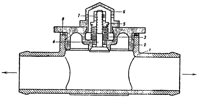
The fuel distributor cock (Plate 11). 9rA=pH%<>B  
The cock serves the purpose of turning on or off the flow of fuel from the tanks to the engine. It is situated on the engine bulkhead at the right. Inside the body of the distributor cock there is a filter (#7) by means of which the fuel is cleaned before reaching the fuel feed pump. The body of the cock has four unions, of these three carry pipes from the fuel tanks and to the fourth is attached the pipe leading to the fuel feed pump. The handle of the tap has four positions (Plate 10): o-Ga3i 8  
1. Handle pointing down - tanks shut off q?ix$nKOv  
2. Handle to the left - petrol flows from front left tank. <=,6p>Eo[  
3. Handle to the right - petrol flows from front right tank. vz!s~cAt  
4. Handle pointing upwards - petrol flows from feed tanks. Q6r7.pk"SU  
The positions right and left are taken facing the front of the vehicle. pf7it5  
From the cock 10 (Plate 10) the fuel flows to the fuel feed pump 1. The fuel feed pump ensures the transmission of fuel under pressure from the tanks through the filter to the fuel injection pump. It is mounted in the crank-case on the fighting compartment side. For lubricating the gland of the fuel feed pump there is a nipple. RG4sQ0  
The filter 2 (Plate 10) is attached to the front of the engine between the two banks. From the filter a pipe leads off to the pressure gauge. The pressure gauge which measures the pressure of the fuel at the filter is mounted in the instrument panel in the driving compartment. G2FXrkU  
(This plate is currently unavailable) cSm%s  
Plate 12 - Fuel injection pump ]H1I,`=@  
1. Fuel priming lever dYgXtl=#j  
2. Support of fuel priming lever (V HL{rj  
3. Rack bar limiter _x5 3g A  
4. Rack bar &sd}ulEg`  
5. Nut of rack bar limiter jfqopiSi  
6. Split pin securing nut ~T89_L  
7. Control plug of governor casing W='> :H  
8. Union for filler pipe P$-X)c$&  
9. Lubricator for governor 6!(@@^7{*  
10. Air bleeder plug n9xAPB }  
11. oil measurer "T- `$'9  
12. Drilling ,zTy?OQ  
Fuel injection ::/j$bL  
(Plate 12) Alxx[l\<J  
The pump is designed to measure out a fixed proportion of fuel corresponding to the load of the engine and to transmit it under high pressure through the injectors into the cylinders. The fuel injection pump is situated on the engine between the two banks. k Zq!&  
Beginning at 1800-1850 rpm the governor controlling the action of the rack bar 4 of the pump limits the maximum engine revolutions. The maximum number of revs that the governor allows in the advent of a sudden falling off of load does not exceed 2050 per minute. The governor is adjusted so that the engine speed reaches 1800 rpm when working at its maximum capacity. The limiting stop of the stroke of the rack bar and the limiter of the fuel priming lever are sealed. It is categorically forbidden to remove the lead seals and change the setting of the limiters. E^ SH\5B  
Lubrication of the components of the fuel injection pump is carried out by means or an oil filler hole in the top of the body of the pump. The oil level in the body of the pump is measured by a dipstick fitted to the filler hole. The normal oil level is between the upper and lower graduations. The pistons and cylinders of the fuel injection pump are lubricated directly from the fuel itself. The governor is lubricated by oil, filled into a casing through the lubricator (#9) {Plate 12) which is fitted to the upper casing of the governor. Oil should be filled into thc casing of the governor up to the level of the control plug (#7). 2TA*m{\Hr  
The fuel reaches the injectors (#8) (Plate 13) from thc fuel injection pump through a thick-walled steel tube. ^) s2$A:L  
/ID?DtJ  
Plate 13 - Layout of fuel system NW&b&o  
1. fuel feed pump %p 0xM  
2. Low pressure pipe Ho *AAg  
3. Fuel filter ]S5JUAGkE*  
4. Low pressure pump @#-q^}3  
5. Fuel injection pump type HK-1 x UD-iSY  
6. High pressure pipe $81*^  
7. Injector union Vkc#7W(  
8. Injector 9,"L^W8"k  
9. Combustion chamber
Air Pressure Pump L:'J Bhg  
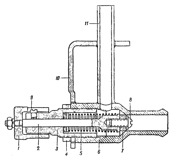
Before starting the engine it is necessary to have the filter and all pipes leading from the tanks to the fuel injection pump primed with fuel. This entails the transmission of fuel from the tanks to the fuel feed pump. The pressure necessary to do this is 0.2-0.3 atmospheres. The hand operated air pressure pump (Plate 14) which is fitted in the front or the vehicle is used to supply this necessary pressure in the tanks. From this pump (#12) (Plate 10) a pipe leads to thc air cock (#13). aVd,xl  
Air distributor cock The cock is fitted on the left of the driver. Its purpose is to link the appropriate fuel tank to the air pressure pump in order to put it under pressure for starting purposes and also to connect the tanks to the atmosphere during the time the engine is running. *C:|X b<9  
The cock has five unions. To one union, the lower one, is connected the pipe from the air pressure pump, to three unions are connected pipes from the fuel tanks and one is connected to the bleeder tap J`^I./  
By turning the handle of the cock, one or the other of the fuel tanks can be connected to the air pressure pump, the remaining tanks are joined to the atmosphere through the opening in the body of the cock. When the position of the handle is against "MA" all the tanks are connected to the atmosphere and the air pressure pump to the air outlet cock. The other positions of the handle are marked thus: 2Roc|)-47  
# "J" - Left tank. c7FRI0X  
# "N" - Right tank. 9\DQ>V TQ  
# "3" - Feed tanks. aT$9;  
For bleeding the air from the fuel filter and the fuel injection pump there is a small tap on the instrument panel (#14) (Plate 10). Air can reach the fuel filter and fuel pump either when stationary owing to there being no fuel in the pipes or when moving through the pipes being air locked when the tanks are low. TG5XSy  
The bleeder tap consistes of a three-way cock with three unions. The unions connect pipes leading from the fuel filter, air pressure pump and the small bleeder tank. fP `b>]N_  
.>IhN 5  
Plate 14 - Air pressure pump ~((w?Yy"v  
1. Hand lever I'0@viF"Nx  
2. Rod _> *j H'  
3. Upper cap =%BZ9,l  
4. Body IyLx0[:U  
5. Spring $ <#KA3o\  
6. Piston 6efnxxY}sa  
7. Lower body UCClWr  
8. Ball &HY+n) o  
9. Valve spring e[#j.|m  
10. Adaptor dB5b@9*  
11. Pipe SE~[bT  
To expel air from the fuel filter before starting it is necessary to build up a pressure of 0.2- 0.3 Kg/cm2 in the tank which is switched on by the distributor cook and to turn the bleeder tap to the position marked "CIIYCK BO3AYXA"(Air out). (See plate 10 and the plate on the instrument panel). Under force of the pressure created in the tank, air, and afterwards fuel, goes from the fuel filter through a small tube, passing the pressure gauge, to the bleeder cock and through this to the bleeder tank. Air first goes through into the bleeder tank, then fuel and air and finally, only pure fuel. In order to eliminate air bubbles it is necessary for the handle of the tap to be in the working position (pointing downwards). If all the air has not been successfully removed from the fuel injection pump by means of the bleeder tap then it is necessary to open the engine hatch and withdraw the plug 10 (Plate 12). After releasing the air from the pump the plug should be replaced. d8x\  
The position !IIPOAYBKA' (inflate) of the bleeder tap should only be used if the fuel oil congeals in the pipe leading to the pressure gauge. To blow out this pipe it is necessary to disconnect it from the fuel filter, set the handle of the bleeder tap to "IIPOAYBKA" and the air cock to "MA" and blow the pipe out by means of the air pump. The small bleeder tank is painted yellow and is positioned in the nose of the hull behind the instrument panel. ez6EjUk  
Fuel injection pump controls The fuel injection pump controls regulate the quantity of fuel entering the cylinders. The lay-out of the control system is seen in (Plate 15) }7.PH'.8  
享生一世澜陨阔
斯年寸草何足灼
留待后世话今昔
烈风细雨笑声谈
顶端 Posted: 2008-09-09 12:15 | 3 楼
vonreynard
匈牙利人民共和国国民议会主席团主席
第一次社会主义劳动英雄称号 十月革命勋章 第一枚劳动红旗勋章
级别: 贵宾/顾问/元老


精华: 2
发帖: 1011
爱心: 1011 点
金钱: 10400 卢布
好评度: 0 点
国籍门派: 匈牙利人民共和国
在线时间:649(小时)
注册时间:2007-11-23
最后登录:2011-07-21


Plate 15 - Fuel injection pump controls N<-gI9_  
1. Foot pedal xe` </  
2. Tie-rod 1BpiV-]=  
3. Lever on the lower bracket 4QIX19{"  
4. Lever ry`z(f  
5. Lower vertical tie-rod b KN@j'M  
6. Upper lever /Y7<5!cS  
7. Upper vertical shaft 'GS"8w~j  
8. Lover +yD`3` E  
9. Tie-rod n74V|b6W  
10. Forked lever 428>BQA  
11. Spring io{@^1ab  
12. Hand lever -RvQB  
13. Fork EKsT~SS  
14. Support for rod 1NgCw\  
15. Rod @8pp EFw  
16. Supporting bolt |~vI3]}fx  
17. Vertical springOn depressing the pedal (#1) the fuel priming lever on the fuel injection pump is operated by means of a system of tie rods and levers. W)f/0QX}W  
On releasing the pedal the spring (#11) returns the control to its original. position provided that the hand lever (#12) does not limit the movement of the tie-rod (#2). The hand lever (#12) is set to a minimum number of engine revs so that on releasing the pedal the engine will not fade. 1R1 z  
Adjusting the fuel injection pump controls r 0iK  
1. Disconnect the tie-rod (#2). =t H:,SH  
2. Pull the fuel supply hand lever (#12) right back. S9~ +c  
3. Alter the length of the tie-rod (#2), set the lost motion device (#10) to the extreme rear so that it is in the zero position (the lever resting on the body of the pump). esMX-.8Cx  
4. With the pedal pushed right down (so that it rests on the footboard) join the front end of the tie-rod (#2) to the pedal (#1). jGpN,/VQa  
5. With the bolt (#16) set the pedal (#1) to the extreme forward position so that the fuel supply lever on the pump reaches the stop (#2) (Plate 12) of the set screw. ei[j1F  
6. Test to see that the travel of the horizontal tie-rod is 18-20 mm. s pp f  
([m mPyp>L  
Plate 16 - Air Cleaner I ,z3xU  
1. Air Cleaner. O4V.11FnW  
2. Lower vessel xY^ %&n  
3. Upper detachable cover. ne_TIwfw-  
4. Upper mesh 9|gr0&#~j  
5. Lower mesh f m)pulz  
6. Wire wool. mSb#Nn6W  
Air Cleaner t_$2CRG#  
(Plate 16) A"G 1^8wvX  
The air cleaner serves to purify the air from dust before it enters the cylinders. The air cleaner is supported on brackets welded to the inlet manifold. Thc basic filter element is oiled wire wool. Tanks of the latest modal (with V-2 engine) also have in the transmission compartment two "Cyclone" air cleaners. \Yc'~2n  
Action of the engine feed system 'DL`Ee\  
When the engine is running the fuel feed pump of the rotary type 1 (Plate 13) supplies fuel from the tank to the fuel filter 3 under a pressure of 0.5 -0.7 Kg/cm2. The filtered fuel goes on to the fuel injection pump 5. In conformity with the firing order and the load of the engine, the fuel injection pump forces at high pressure the necessary quantity of fuel into the injectors. Maintenance of the engine fuel system. The main defects of the fuel feed system are due to obstructions in the fuel pipes owing to bad engine maintainece. The following points must be watched : G'ei/Me6{  
1. In filling the tanks with fuel attention must be paid to the instructions given in chapter VII under the heading "Filling up". [8*jw'W|[  
2. Every time the vehicle returns from a journey it is necessary to test the tanks, cocks and examine the whole system for damage. To test the air tanks and pipes, apply a pressure of 0.2-0.3 Kg/cm2 and watch the pressure gauge for 2-3 minutes. If after this period the pressure does not subside then there is something wrong with the system. E(8* pI  
3. After every 10 hours of engine running it is necessary to examine and clean the mesh filter (#7) (Plate 11) in the distributor cock. +>{Y.`a;Jo  
4. After every 25 hours of engine running it is necessary to clean the fuel filter. P>NF.B Cq  
5. After every 50 hours of engine running, the fuel tank drain plugs should be unscrewed and sediment removed. [k;\SXDZo  
If any defects occur in the fuel injector pump, the fuel feed pump and the fuel injector pump should be detached and handed over to a base workshop or to a special fitter. 6&!PmKFO.  
The air cleaner should be periodically cleaned. The period depends on the terrain and time of the year. In summer when the atmosphere is dust laden, the air cleaners should be cleaned and oiled after 10 hours of engine running. In the winter only after 20-25 engine running hours. The air cleaners should be cleaned with kerosine. SfaQvstN  
9vGu0Um  
Plate 17 - Lubrication System \Ani}qQ%|  
1. Oil pump Ne[7gxpu  
2. Oil radiator tank dE4L=sTEsy  
5. Change-over cocks G2Qlt@.T  
6. Filler plug q$B>|y U  
7. Threaded grease guns for lubricating the spindle of the water pump 3 +G$-ru  
8. Compensating tank uYs5f.! `  
9. Junction pipe 'z%o16F)L  
10. Fresh oil thermometer =pS5uR~  
11. Used oil thermometer 1]@}|  
12. Pressure gauge )\J+Kiy)  
ENGINE LUBRICATION SYSTEM )W;o<:x3  
For the lubrication of the engine, "Avia" Oil MK and M3 is used in the summer and M3L in the winter. HiR[(5vnf  
The lubrication system (Plate 17) consists of two oil radiator tanks 3, oil pump 1, oil filter 2, pressure gauge 13, two thermometers 11 and 12, and a compensating tank 9. In the latest models, oil tanks are not in the form of radiators (i.e. without cooling fins), and the change-over cock is not fitted. V4'YWdTi  
Construction of Lubrication System The oil radiator tanks These are situated in the engine compartment at the sides. Their inner surfaces (facing the engine) are fitted with laminated fins (or radiator sections) where possible. The full capacity of each tank is 57 litres. The minimum possible quantity of oil is 10 -15 litres. A dipstick is provided and is inserted in the filler plug in the oil tank. In the bottom part of the tank there is an oil filter. At the base of the filter there is a threaded drain plug 7. To remove the oil from the tank this plug should be unscrewed two or three turns - it is not necessary to unscrew it completely - and the oil will flow from the opening. The inside of the plug is adapted to take a hose for draining the oil into a vessel. The filler has a mesh filter. The top of the tank has a change-over cock the handle of which has three positions: 5n9B?T8C  
1. Forwards (towards the front of the vehicle) - oil can be forced directly by the pump through the cock into the tank. 2. Backwards - radiator on. The oil is cooled to air temperature as it flows through the radiator fins and it passes into the oil tank to be taken up again into the engine. 3. To the side - the tank and radiator are shut off. &)AVzN+*h  
When the engine is running the handles of the change-over cocks 5 (Plate 17) of both tanks (those which have radiators) must either be in the position "HA BAKN" (to tank) or "HA PADNATOR" (to radiator), it is forbidden to leave the handle pointing to the side. eQp4|rf  
The junction tube 10 serves to connect both tanks to the crankcase and also to drain off oil and foam when the tanks are overfull. /7|V+6jV  
The oil pump which is fixed to the crankcase bottom half serves to force oil under pressure to the engine and to scavenge the used oil. #/Vh|UeX  
~l]ve,W[  
Plate 18 - Oil Filter 0c<.iM  
1. Body rMLp-aR'  
2. Cap ~nh:s|l6%M  
3. Adaptor for inlet pipe jw^<IMAG\8  
4. Adaptor for outlet pipe \%f q  
5. Union for safety valve Wp!%-vzy&  
6. Filter disc with rim outside =,_ +0M9  
7. Nut 8T!+ZQAz  
8. Central stud NnDxq%l%  
9. Union B1>/5hV}  
10. Filter disc with rim inside. +RYls|f  
The oil filter (Plate 18) is attached to the front of the crankcase bottom half. !`,Sfqij  
Action of the lubrication system &h^9}>rVjV  
Both pairs of scavenge gears in the oil pump force oil into the compensation tank (#9) (Plate 17) whence it flows through the change-over cock (#5) into the tank-radiators. The compensation tank serves to return the used oil equally to both tanks. The pressure of the oil system which is indicated in the pressure gauge must be 6-9 Kg/cm2. This oil pressure is obtained by the help of the relief valve situated underneath the top or the oil pump. The temperature of the oil entering the engine (thermometer #11) must be more than 40oC and must not exceed 80oC The temperature of the oil leaving the engine (thermometer #12) must not exceed 100C. ]pNvxXbeW  
In certain exigencies it is possible to fill not more than 5-6 litres of oil directly into the crankcase through the breather. The spindle of the water pump should be lubricated periodically by thc threaded grease gun (#3) (Plate 17). LXC9I/j/  
p8h9Ng* &`  
Plate 19 - Plan of Engine Lubrication Of[XKFn_  
N.B. In V-2 -S4 (Series H) engines, the lubrication is conducted from the front. D*gFV{ Ws  
ENGINE COOLING SYSTEM 5 ft`zf  
The engine cooling system (Plate 20) is comprised of the water jacket of the cylinder blocks, water radiator (#1), water pump (#2) with cock (#3), centrifugal fan (#14), T-piece (#8) with air valve, steam valve (#12) and pipes. The capacity of the cooling system is 90-95 litres. ;7 E7!t^  
Construction of the Cooling System uj R_"r|l  
Radiators C1m]*}U  
Two tubular type radiators are installed in the vehicle inclined at each side of the engine. =WyZX 7@R  
Each radiator consists of two collector tanks at the top and bottom connected to each other by copper tubes. To increase the cooling surface of these tubes, they are covered with thin copper laminations. S~;4*7+?:  
The lower collector tank of the radiators are joined by pipes to the water pump. -xEXN[\S  
The top collector tank of the radiator has two pipe connections, one to the jacket, the other to the T-piece for draining water from the radiator. In the middle of this collector tank there is a union to which is joined to a thermometer. The top right collector tank has, in addition to these pipe connections, yet another pipe for leading off steam to the steam valve and an inspection plug for testing the level of the water. +#lM  
The centrifugal fan is mounted on the flywheel and servee to blow air round the water and oil radiators. ymx>i~>7J  
享生一世澜陨阔
斯年寸草何足灼
留待后世话今昔
烈风细雨笑声谈
顶端 Posted: 2008-09-09 12:16 | 4 楼
vonreynard
匈牙利人民共和国国民议会主席团主席
第一次社会主义劳动英雄称号 十月革命勋章 第一枚劳动红旗勋章
级别: 贵宾/顾问/元老


精华: 2
发帖: 1011
爱心: 1011 点
金钱: 10400 卢布
好评度: 0 点
国籍门派: 匈牙利人民共和国
在线时间:649(小时)
注册时间:2007-11-23
最后登录:2011-07-21


Plate 20 - Engine Cooling System JJ}0gZ   
1. Water radiators Rot@x r7Hc  
2. Water pump s>;v!^N?u  
3. Drain cock >}`:Ac  
4. Drain pipe h]+C.Eqnt#  
5. Pipes bJRN;g  
6. Pipes supplying the pump ` k[-M2[  
7. Hose connection ("durite") for filter h{HF8>u[  
8. Filler T-piece 8+a4>8[M  
9. Pipes taking water from engine < Z{HX[y  
10. Pipes taking steam from the cylinder heads -+ SF  
11. Pipe for taking off steam from the radiators \`oT#|0  
12. Steam valve Cjqklb/  
13. Lead to drain cock ej4W{IN~:  
14. Centrifugal fan.The air valve with T-piece filler (#1) (Plate 21) is connected to both radiators and is designed for filling up with water. In the cover of the T-piece an air valve is fitted adjusted to operate at pressures of 0.08- 0.13 Kg/cm2 lower than atmosphere. Thus it is impossible for a pressure lower than atmosphere to form inside the radiator as a result of the rapid cooling of the system when the engine is stopped. C([phT;  
l6YtEHNG  
Plate 21 - Filler T-piece with air valve 01r 8$+  
1. T-piece e+$p9k~  
2. Body of air valve I/d&G#:~  
3. Spring k2c}3 MeP  
4. Valve 8jd;JPz@\  
5. Nut b$ve sJ  
6. Cap xy5lE+E_U  
7. Split pin 10<x.8fSP  
8. Packing 1|kvPo#  
a`&f  
Plate 22 - Steam Valve  `x l   
1. Nut sYe?M,  
2. Valve spindle 0E,8R{e  
3. Adjusting nut {sihus#Q  
4. Chock nut "= 6_V?&w  
5. Spring .y_/Uwu  
6. Body of valve r@v,T8  
7. Rubber valve @&%'4j&+  
8. and 9. Screws hd>aZ"nm1  
10. Bracket p7veQ`yNc  
11. Steam escape pipe <3xyjX'NE  
The steam valve (Plate 22) is fitted to the upper half of the engine Compartment bulkhead. The body of the valve is connected to the steam escape pipe of the right radiator. The steam outlet pipe (#11) of the valve leads outside through a hole in the hull of the tank. K/tRe/t }  
The nut (#1) of the valve serves as a control and is situated inside the fighting compartment. ;> _$`  
The steam valve is adjusted to open at pressures of 0.6-0.8 atmospheres above atmospheric pressure, thereby safe-guarding the radiators from internal pressure. 4}_j`d/8|  
When filling up and draining off water, it in necessary to turn the nut (#1) to the right or left so that the cooling system is connected to the atmosphere. When filling up or draining off is finished. the steam valve must be closed again by screwing up the nut. OMWbZ>jB  
Starting up the engine by compressed air The compressed air system is an alternative method of starting the engine and is used when the electric starter will not work. NO|KVZ~  
CONSTRUCTION AND ACTION OF COMPRESSED AIR STARTING SYSTEM *5vV6][  
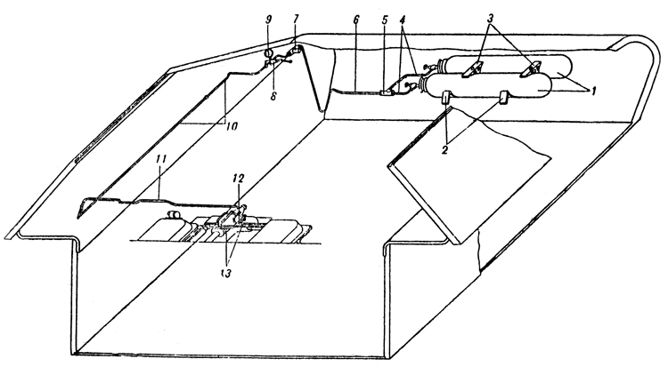
The system of starting the engine by compressed air (Plate 23) consists of two compressed air bottles, a reduction valve (#8), pressure gauge (#9), air distributor to cylinders (#12) (mounted on the engine), pipes (#13) from the air distributor to cylinders and twelve outlet valves (one for each cylinder). lD^]\;?  
The compressed air bottles are fitted on special brackets (#2) in the nose of the tank. u [m  
The capacity of each bottle is 10 litres and the maximum pressure in the bottle is 150 atmospheres. Each bottle has a valve by means of which it is connected to the control system. Air from the bottles travels through the pipe (#4) to the T-piece (#5) and to the reduction valve. 4 Y ;Nm1 @  
The T-piece is designed for refilling the bottles with air without removing them from the vehicle. P<l&0dPO8  
The reduction valve (#8) is designed for adjusting the air pressure at the air distributor of the engine. It is mounted at the left of the driver. ?u/@PR\D  
The pressure gauge which reads up to 250 atmospheres indicates the pressure in the bottles (when the valves are opened). Procedure for starting the engine by compressed air is described in Chapter VII - Maintenance. A<5ZF27  
so"$m  
Plate 23 - Layout of Compressed Air Starting System i5Zk_-\#H  
1. Compressed air bottles o.w\l\  
2. Brackets ,sA[)wP{  
3. Clamps ^B(V4-|  
4. Pipes <j&DK2u=i  
5. T-piece #33fGmd[  
6. Pipe Connecting T-piece ]+|~cRQ9I  
7. T-piece for filling air bottles @hJ%@(  
8. Reduction valve Q<h-FW8z  
9. Pressure gauge 4wID]bKM  
10. Pipe l>Z5 uSG  
11. Transverse pipe 9K5pwC\$%  
12. Air distributor GNXHM*~  
13. Pipes connecting air distributor to cylinders. w[9|cgCY  
Care of the Compressed Air Starting System Gb8D[1=u=  
It is necessary to test the air pressure in the bottles periodically during inspection of the vehicle. 'MEz|Z  
The pressures in the bottles must not be lower than 40 atmospheres in the summer and not lower than 60 atmospheres in the winter. The pressures should be increased in the case of a worn engine. If the pressure is lower than instructed, starting will be made more difficult. /2UH=Q!x4E  
INSTRUMENT PANEL U]^HjfX\  
The instrument panel carries the following instruments : OTGofd2zf  
1. Two pressure gauges of which one indicates the fuel pressure and the other the oil pressure. |B'9\OkP[=  
2. Three aero-thermometers of which one indicates the temperature of the oil entering the engine, one the temperature of the oil leaving the engine and the third the temperature of the water leaving the engine . O4r0R1VQM  
3. Tachometer showing the revs of the crankshaft. )~+E[|  
4. Clock. A speedometer is mounted on the suspension casing of the left front bogie wheel. {;N,t]>8M  
P|.]DJ  
Chapter III. TRANSMISSION
Xf02"PXC  
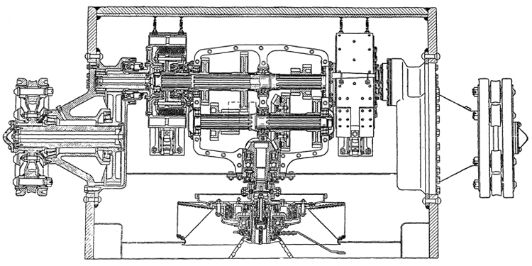
Plate 24 - Transmission of the tank |zQ4u  
ENGINE CLUTCH !lf|7  
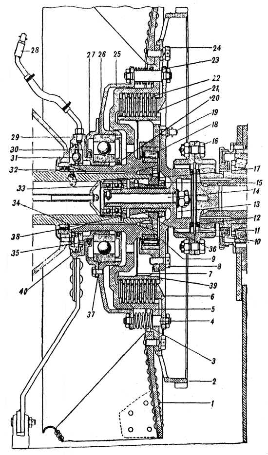
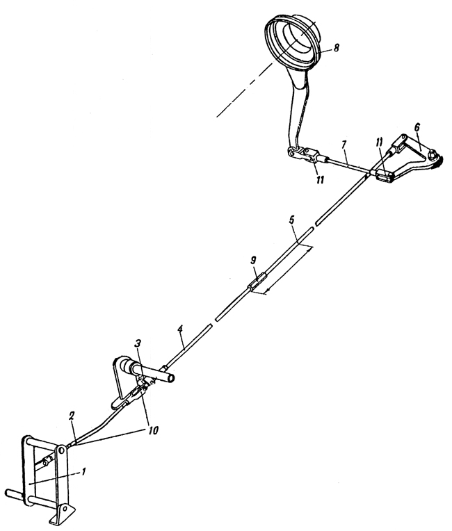
The engine clutch is multiplate, dry with steel friction plates. It consists of driving and driven parts and a withdrawal mechanism. The operation of the clutch from the driving compartment is carried out by means of a linkage (Plate 26). jT8#C=a7  
g .onTFwN  
Plate 25 - Engine Clutch m@"QDMHk.  
1. Fan XWA:J^  
2. Starter ring J?RabYd ~  
3. Spring "} q@Y=  
4. Stud N}pw74=1  
5. Flywheel jX3,c%aQ5e  
6. Pressure plate tSVc|j  
7. Oil excluder plate 2"Ecd  
8. Bolt JRSSn]pw  
9. Cone q*F{/N **  
10. Coupling cxA^:3  
11. Ring q#vQv 5  
12. Packing LV\DBDM  
13. Hub IhA5Wt0j  
14. Scouring bolt d]:I(9K  
15. Nut rs,2rSsg!  
16. Fitted bolts 2_n7=&  
17. Plug Y' %^NP}o  
18. Roller bearing O\E/. B  
19. Lubricator \@8+U;d  
20. Gland (yF:6$:#  
21. Driven plate &j4xgh9  
22. Driving plate K8>zF/# +  
23. Lock washer N['qgO/  
24. Bolt ^cczJOxB  
25. Disengaging plate 85n1eE  
26. Ball bearing SnE(o)Q  
27. Cover 5jd,{<  
28. Lubricator tNGp\~  
29. Control box >#hO).`C  
30. Fixed face cam r<K(jG[:{f  
31. Ball of withdraw mechanism NWM8[dI  
32. Cone 4 !y%O  
33. Ball bearing k.uMp<)D  
34. Packing xnmmXtk  
35. Gland .2%zC & ;  
36. Conical plug MYla OT  
37. Packing r30 <(nF  
38. Nut Y( 3Bp\6  
39. Driven drum 0Uo\wyd  
40. Cast iron ring B$b +Ymu  
The driving plate of the clutch comprises of (Plate 25): flywheel (#5), disengaging plate (#25), pressure plate (#6) and ten steel driving plates (#22). The flywheel is seated on splines of the crankshaft, it is centered on it by two bronze cones (#9) and (#32) secured by a plug (#17) which is located by the cone (#36) tightened by the nut (#15) screwed on to its stem. n` xR5!de  
To safeguard against the cone moving and tightening the nut (#15), there is a dowel that fits into one of the slits of the plug (#17). |K.mP4CKY  
The internal surface of the flywheel is splined to mesh with the teeth of the driving plate (#22). Around the flywheel plate are positioned sixteen holes for the studs (#4). The fan (#1) is fitted to the flywheel plate on the side of the engine and on the side of the gearbox a toothed ring for the starter. '+osf'&  
The fan is secured by 27 bolts, of which 24 are used to secure the toothed starter ring. .WPV dwV4U  
The disengaging plate (#25) and the pressure plate (#6) have sixteen holes. These plates (#25) and (#6) are joined to each other by the studs (#4) and are secured by nuts. The springs (#3) pressing against the friction plates are carried on the studs between the flywheel and disengaging plate. Between the shoulders of the studs (#4) and the pressure plate two washers (#13), 0.5 mm. are fitted. These washers are designed for the normal maintenance adjustment of the clutch. EQf[,  
The driving plates (#22) are made of steel; their outer circumferences are splined and are in mesh with the teeth of the flywheel. Thus all the driving components of the engine clutch rotate in one piece with the crankshaft. V'kX)$  
The driven parts of the clutch comprise of: The driven drum (#39), with hub (#13) and twelve steel driven plates (#21). ppZDGpp  
The outer surface of the driven drum is splined and in mesh with the teeth of the driven plates. On the outside, the driven drum is connected to the hub, (the end of which is splined), by means of eight bolts. f !s=(H;  
The driven drum runs on a ball bearing (#18) seated on the hub of the flywheel. (In tanks of the first model the driven drum had two supports; a roller bearing on the hub of the flywheel and two ball bearings in the end of the crankshaft, through the tail piece of its hub, the driven drum rested on these bearings. Z @^9PQG$  
The connection between the driven drum and the driving shaft of the gearbox is in the form of a geared tooth coupling (#10). One half of the coupling meshes with the tooth of the hub (#13) and the other half with the gear of the driving shaft. Both: halves of the coupling are connected to one another by fitted bolts (#16). D+>4AqG  
The driven plates have teeth, the inside of which mesh with the toothed driven drum. All the driven plates of the engine clutch rotate in one piece with the driving shaft of the gearbox. q:dHC,fO  
Withdrawal mechanism of the engine clutch comprises of: ]}U*_rM:  
# fixed face cam (#30) Z&|Kki*  
# separator with three balls (#31) /9HVY %n  
# control box (#29). X:6c}p%,!  
The fixed face cam is bolted and doweled to the crankcase. {B[=?6tQ  
The control box is a press fit in the inner race of the ball bearing (#26) the outer race of which, is housed in a seating of the cover of the disengaging plate provided with felt ring oil seals. To the control box a grooved ring of special shape is fitted for balls. In the fixed face cam there are also grooves of the same shape on the other half of the face cam. 2Ou[u#H  
Between the fixed face cam and the control box there is a separator with balls which run in the grooves. B[V+ND'(  
Note. In T-34 tanks with M-17 engine, the engine clutch is the BT type. W_kHj}dj,p  
&;+ -?k|  
Plate 26 - Engine Clutch Control Linkage p1&b!*o-&  
1. Pedal LL2=&VK  
2. Inclined rod BReJ!|{m}  
3. Supporting lever +6';1Nb@  
4. Front part of long tie-rod kKAP"'v  
5. Rear part of long tie-rod D@Vt^_  
6. Double arm lever (vb SM}P  
7. Transverse lever LG<J;&41~S  
8. Control box |2abmuR0  
9. Adjustment ~kZ G{  
10 & 11. Feed joints xYmxc9)2  
Adjustment of the clutch. A. To adjust the clearance in the balls of the withdrawal mechanism to within 0.9 -1.1 mm. 1. Unscrew the nuts securing the spring loaded studs (#4). 2. Remove the pressure plate. 3. Remove one adjusting washer from each stud. 4. Replace pressure plate. w *oeK  
If the travel of the tie-rod measures from 20 - 25 mm then the clearance in the balls of the withdrawal mechanism will be from 0.9 -1.1 mm. W7 Cc  
B. To adjust the travel of the pressure plate to 6 to 7 mm. 1. Adjust the fork (#10) on the inclined tie-rod. 2. Alter the adjusting nut (#9) on the long tie-rod. |QU <e  
GEAR BOX nq6@6GRG  
Translator's Note: The gearbox is of normal sliding mesh type of a very usual design with four speeds forward and one reverse and it has not been considered necessary to make a full translation of its description. c17_2 @N  
The gearbox casting is of aluminium and made in two halves. Recently it has been made of cast iron. `}mcEl  
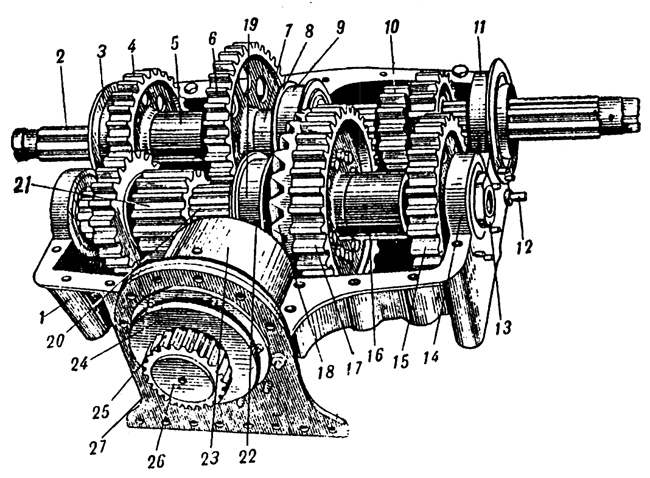
It is operated by a selector mechanism (Plate 30) on the right of the driver to which is fitted a lock to prevent reverse gear being accidentally engaged when moving forward. ~NQ72wph{  
享生一世澜陨阔
斯年寸草何足灼
留待后世话今昔
烈风细雨笑声谈
顶端 Posted: 2008-09-09 12:16 | 5 楼
vonreynard
匈牙利人民共和国国民议会主席团主席
第一次社会主义劳动英雄称号 十月革命勋章 第一枚劳动红旗勋章
级别: 贵宾/顾问/元老


精华: 2
发帖: 1011
爱心: 1011 点
金钱: 10400 卢布
好评度: 0 点
国籍门派: 匈牙利人民共和国
在线时间:649(小时)
注册时间:2007-11-23
最后登录:2011-07-21


Plate 27 - General View Of The Gearbox (Without The Top Half Of Its Case) X pBj%e:  
1. Casing, lower half d` jjGEj  
2. Main shaft wid;8%m  
3. Outer race of main shaft bearing A29gz:F(  
4. Fixed gear of 2nd speed 2T V X)q<\  
5. Spacer bush !V i@1E  
6. Fixed gear of 1st speed . 1 D<_N  
7. Spacer bush Si6al78  
8. Ring of cover of conical bearing X@K-^8  
9. Cover of conical roller bearing of central support .HkL2m  
10. Moving gear train for 3rd and 4th speed ha(Z<  
11. Cover of roller bearing of outside support cm&I* 0\  
12. Limiter of control box for disengaging steering clutch t.`@{R$hoA  
13. Nut YKO){f5  
14. Roller bearing of outside support bO'Sgc[]  
15. Fixed gear of 3rd speed fjs [f'L  
16. Spacer bush `Ye\p6v!+  
17. Fixed gear of 4th speed w*oQ["SL  
18. Driven bevel gear 6WU(%  
19. Cover of intermediate shaft UrYZ` J  
20. Intermediate shaft uF1~FKB  
21. Moving gear train for 1st and 2nd speeds :=wT vz  
22. Driving bevel gear RPE5K:P  
23. Cover of driving shaft e^<#53!  
24. Gland nut N6 (  
25. Geared coupling a hR ^  
26. Plug HN&Z2v   
27. Bracket (`sH3&Kl  
Plate 28 - Gearbox (Section Through Casing) 1:f9J  
1. Main shaft l}] t~!X=  
2. Gear train of 3rd and 4th speeds 1n:8s'\  
3. Conical roller bearing }M3fmAP}  
4. Cover of main shaft roller bearing _Jme!Oaa  
5. Nut [^U#Qj)hL  
6. Spacer bush }^/9G17  
7. Fixed (driven) gear of 1st speed eC[$B99\  
8. Spacer bush n&-qaoNl  
9. Fixed gear of 2nd speed ni<A3OB  
10. Cover of outer supporting cylindrical roller bearing fO0XA"=  
11. Roller bearing 9Hc$G{[a  
12. Packing ring /4` 0?/V  
13. Ring y5do1Z  
14. Gland P DrZY.-  
15. Fixed face cam of steering clutch disengaging mechanism Qzlo'e1  
16. Thrust ring m0cP(  
17. Bush h $L/<3oP6  
18. Intermediate shaft S5G6Rj@W  
19. Nut bpKZ3}U  
20. Roller bearing %2XHNW  
21. Fixed gear of 3rd speed |aT| l^2R@  
22. Spacer bush ;K!]4tfJ  
23. Fixed gear of 4th speed b0Kc^uj5  
24. Driven bevel gear (&+kl q  
25. Cover of conical roller bearing of intermediate shaft W!6qqi{  
26. Conical roller bearing ?sMP~RHQ  
27. 1st and 2nd speed gear train :yeq(o K,  
28. Roller bearing Bh=u|8yxc  
29. Cover ~:3QBMk::  
30. Thrust ring fp[|M  
31. Adapter ring nIU6h  
32. Driven shaft 34d3g  
33. Cover rim D (h18  
34. Roller bearing B:!W$ <  
35. driven roller bearing pBETA'fY  
36. Ball bearing X!m9lV<  
37. Spherical ball bearing ~[\_N\rm  
q.2ykL  
Plate 29 - Gearbox (Section Through Reverse Gear Train) b#K:_ac5  
1. Reverse gear train IFDZfx  
2. Roller bearing %=/)  
3. Ring nut Yx eOI#L  
4. Floating washer }lfnnK#  
5. Shaft of reverse gear train Vzwc}k*Y  
6. Set screw IGtl\b=  
7. Plate $D}{]MN.  
= Wu *+paQ  
Plate 30 - Gear Selector IuNiEtKx  
1. Base. of gear selector l&?}hq^'Dn  
2. Casing ^V#@QPK9  
3. Spherical nut c2e tc8  
4. Protecting cover |b|&XB_<]Z  
5. Flexible cover GQ9\'z#+  
6. Cable K9OYri^TQ  
7. Locking handle k[HAkB \{  
8. Gear selector hand lever KN7n@$8YM  
9. Ball and socket joint .8P.)%  
10. Plate spring j{Txl\D>  
11. Horizontal selector rods *X, /7C   
12. Locking ball  }(1JaG  
13. Locking plugs m"o ;L3  
14. Locking catch %Mk0QKzUo  
15. Looking spring pb$~b\s]=  
16. Rotating plate V}SBuQp"  
17. Spindle of rotating plate }w1~K'ck}>  
18. Return spring 3 AsT  
19. Cover of locking gear sK7+Q  
20. Gear lever 1;mW,l'`  
21. Bolt rxy&spX  
22. Check nut iv>SsW'p_  
23. Ball of look p\JfFfC  
24. Bracket Q)LM-ZJKQ  
25. Retaining latch for reverse gear IaT$ 6\>  
mL_j4=ER@  
Plate 31 - Action Of Gear Selector Locking Device 4Rvf  
# 1st Position Handle not compressed. The rotating plate does not allow the locking catch to move upwards. D;_ MPN[  
# 2nd Position Handle compressed against the lever. The rotating plate is turned and an aperture is brought immediately over the catch. JXu$ew>q  
# 3rd Position Handle compressed against the lever. On moving the horizontal lever the ball is forced up and the catch mates with the aperture in the rotating plate. ]Yvga!S"C  
# 4th Position Gear engaged. ball returns to socket under pressure of the spring and rotating plate returns to normal position . Xt#4/>dlR  
[&nh5 |f  
Plate 32 - Action Of Gear Selector Lock ;uW}`Q<  
1. Neutral. }b0; 0j  
2. Central horizontal lever is moved. End levers are closed. S p^9& ^  
3. Right horizontal lever moved. Central and left levers are closed. \l.-eu'O  
9\]^|?zQ`  
Plate 33 - Vertical Shafts w*|7!iM  
1. Tie-rod of 3rd and 4th gears 4qYUoCR&  
2. Tie-rod of reverse gear IjR'Qou5  
3. Tie-rod of 1st and 2nd gears Qbyv{/   
4. Bottom lever of reverse gear e{v=MxO=S  
6. Bottom lever of 1st and 2nd gears yRiP{$E  
7. Shaft of 1st and 2nd gears &d5ia+ #  
8. Shaft of reverse gear JM\m)RH0  
9. Shaft of 3rd and 4th gears ngat0'oa  
10. Top lever of 1st and 2nd gears GF5^\Rf  
11. Top lever of reverse gear sRrzp=D  
12. Top lever of 3rd and 4th gears 1$81E.  
13. Bracket ea~:}!-P  
14. Lubricator i}o[- S4  
15. Tie-rod for 1st and 2nd gears _<NMyRJo  
16. Tie-rod for reverse 2c:#O%d(  
17. Tie-rod for 3rd and 4th gears :P@rkT3Qt  
18. Cranked lover for 3rd and 4th gears * ;Cy=J+  
19. Tie-rod for 3rd and 4th gears *H.oP  
20. Ball )J NSZB  
22. Pin 3l3'bw2  
STEERING CLUTCHES HfvTxaK  
The steering clutches are mounted on the main shaft of the gearbox. The internal driving drum (#3) (Plate 34) is splined on to the intermediate shaft of the gearbox, the external driven drum (#1) is fixed at the edges to the final drive. Between the internal and external drums there is a complete set of twenty-one driving and twenty-two driven plates each of which is geared to teeth of its corresponding drum. y !!E\b=  
The plates are compressed by springs (#19) acting through eighteen studs passing through openings of the plate of the internal, to the pressure plate (#2) seated on studs and fixed by nuts which are locked by flexible washers. The other extremity of the springs rest on the disengaging plate (#18) seated on the same studs and fixed by nuts. The withdrawal mechanism is operated by fixed face cams on the same principle as in the engine clutch (see drawings). W@Lu;g.Yc  
HjGyj/78w  
Plate 34 - Steering Clutch d\FJFMW*9  
1. External driven drum X_g 3rv1J  
2. Pressure plate q7-L53.x  
3. Internal driving drum Pw;!uag  
4. Stud EoxQ */  
5. Steering clutch flange ZG du|  
6. Ring jMN[J|us51  
7. driving shaft ^4`Px/&  
8. Two-point spherical ball bearing gF5a5T,  
9 & 10. Caps with glands ,$ ^C4I  
11. Ball bearing supporting radially hQDTS>U  
12. Control box |)K]U  
13. Withdrawal mechanism ball +C(/ Lyo}  
14. Adjustment [g Z"a*  
15. Ring L[20m (6?  
16. Fixed face cam d R]Q$CJ  
17. Stuffing box pTyi!:g3W  
18. Disengaging plate |R#"Th6mH!  
19. Spring YcN!T"w J@  
20. Lubricator !ZI7&r`u;  
21. Driven plate nYa*b=[.  
22. Driving plate ulER1\W  
23. Washer Wxbq)Z[V  
24. Nut _Jt 2YZdA  
25. Fixed face cam ring & _g TD  
26. Control box ring NU*fg`w  
BRAKES K%Rj8J7|u?  
The brakes which are used for parking, slowing down or steering are in the A6pjRxg  
form of "floating" bands which wrap round the outside of the driven end of the steering clutches. The steel bands are lined with Ferodo. In later models the internal surface of the brake bands have riveted cast iron linings. E)9yH\$6  
The upper ends of the brake bands terminate in an adjusting bolt which is joined to a lug in the control lever and scoured by a pin. rJ!{/3e  
The clearance between the brake band and the drum when the brakes are released should be maintained at 1.5 to 2.0 mm. DANw1 _X\  
Eyh51IB.  
Plate 35 - Brake Band P b]3&!a  
1. Brake band QtJg ^2@  
2. Actuating lever \0H's{uek  
3. Bracket ^=^z1M 2P  
4. Pins *mMEl]+  
5. Adjusting bolt {s_+?<l  
6. Barrel Nut _+^ 2^TW  
7. Spring MiRdX#+Y  
8. Securing arm 0sh/|`\  
CONTROL LINKAGE FOR STEERING CLUTCHES AND BRAKES acw4B5]  
The control linkage for steering clutches and brakes (Plate 36), consists of the following main parts: steering levers (#1) with compensating device compensating shafts (#2) transfer shafts (#3) tie rods o)[2@fRC(  
享生一世澜陨阔
斯年寸草何足灼
留待后世话今昔
烈风细雨笑声谈
顶端 Posted: 2008-09-09 12:17 | 6 楼
vonreynard
匈牙利人民共和国国民议会主席团主席
第一次社会主义劳动英雄称号 十月革命勋章 第一枚劳动红旗勋章
级别: 贵宾/顾问/元老


精华: 2
发帖: 1011
爱心: 1011 点
金钱: 10400 卢布
好评度: 0 点
国籍门派: 匈牙利人民共和国
在线时间:649(小时)
注册时间:2007-11-23
最后登录:2011-07-21


Plate 36 - Layout Of The Steering Clutch And Brake Controls !P$'#5mr  
1. Steering lever with compensating mechanism (?*BB3b`  
2. Compensating shaft o1/lZm{\~n  
3. Transfer shaft 0iZGPe~  
4. Foot bake controlThe steering lever (#1) pivots on a shaft fixed in a bracket. This actuates a small lever (#4), of the foot brake linkage. This small lever is joined to the brake band through other levers connecting to the compensating shaft, tie-rods and levers of the transfer shaft. i#%a-I:M  
The steering levers terminate in hooked levers, the internal working surfaces or which are ramped and bear against rollers fixed to a forked lever which is pivoted in the bracket. (Plate 37) One end of the forked levers is connected to a return spring and the other end to the control rod of the steering clutch. This tie-rod is connected through the compensating shaft, long tie-rod, transfer shaft and control lever to the control box of the steering clutch. \)48904^  
The connections between the separate components of the control linkage are shown in Plate 36. & ``d  
The foot brake control consists of pedals, pedal tic-rods with two projections. One end of the pedal tie-rod is connected to the pedal and the other end to a small control lever (#4) which moves freely at the end of the two compensating shafts. }BmS )J q  
Action of the steering Control x#N-&baS  
When the steering lever is in the extreme forward position, the force of the compensating springs is transferred through the rollers to the bracket. On pulling the steering lever backwards the spring pulls the forked lever forwards and disengages the steering clutch. When the roller reaches the end of the ramp of the hook the disengagement of the clutch is completed and the force of the clutch spring is transferred to the bracket. All the force exerted by the driver is now used to operate the brake. A fixing device is provided to hold the brakes on. _NcY I  
t nS+5F  
Plate 37 - Action Of The Steering Lever ,JEbd1Uf  
A. Force of unloader spring. #DjCzz\  
B. Force of steering clutch spring. 4TwQO$C  
The fixing device (Plate 33) consists of the following parts : bracket (#5), toothed segment (#6), control lead (#7) and return spring (#8).  A, PlvI  
JNFIT;L  
Plate 38 - Pedals Of Foot Brake And Engine Clutch With Fixing Device Y= 7%+WyD  
1. Foot brake pedal tyDY'W\]  
2. Tie-rod j2P n<0U  
3. Bracket iHp\o=#  
4. Shaft 7DfTfTU6  
5. Bracket =5s F"L;b  
6. Toothed segment 2F8|I7R  
7. Control lead pfd#N[c  
8. Spring YUdxG/~'  
Adjustment to the Steering Clutches and Brakes and their Control Linkages 1. The clearance between the balls and the fixed face cam of the withdrawal mechanism of the steering clutch should be between 0.9 and 1.1 mm. 2. The travel (in one direction) of the long tie-rod of the steering clutches should be between the limits of 9 to 12 mm. 3. The clearance between the brake band and the drum should be within the limits of 1.5 to 2 mm. 4. The tie-rod should have 15 to 20 mm. horizontal travel before the brakes are applied. A`u$A9[  
FINAL DRIVE L@^~N$G&u  
The final drive (Plate 39) is mounted in casing (#16) incorporated into the tail of the tank and the hull side plates. The cover (#8) is attached to the casing by bolts. The final drive is a single hub reduction gear which transmits the torque to the sprocket wheel. 6UE(f@  
f):~8_0b  
Plate 39 - Final Drive "|m|E/Z-9  
1. Flange ItX5JV)  
2. Cover z1!6%W_.  
3. Worm <q,+ON\'  
4. Spherical roller bearing Sc]P<F7N]  
5. Driving shaft with gear 2 /y}a#s  
6. Roller bearing dtAbc7  
7. Assembly locking spindle [Lp,Hqi5  
8. Cap of casing K$ v"Uk  
9. Driven shaft . /p|?pu  
10. Filler plug Ft@Wyo`^  
11. Conical roller bearing rz(0:vxwA  
12. Assembly locking spindle CWO=0_>2  
13. Cap dxj*Q "K  
14. Bolt K+T .o6+  
15. Conical roller bearing Se!)n;?7Sw  
16. Casing L}j0a>=x4  
17. Plug of lubricating aperture =_[Z W  
18. Driven gear >bUj *#<  
19. Worm wheel shaft `E\imL  
20. Washer - ~4+w  
21. Bush Y?#i{ixX6n  
22. Flanged bush UHGcnz<  
23. Internal bush 6TH!vuQ1(  
24. Sealing washer <fdPLw;@e4  
25. Speedometer cable casing ba@=^Fa;  
26. Washer 4q$H  
27. Cover of roller bearing k?VQi5M  
28. Sealing ring wVq\FY%  
29. Gland ofW+_DKB?l  
30. Cover of spherical roller bearing LjdYsai-  
31. Sealing ring >x[`;O4  
32. Pressure ring of gland Q!M)xNl/  
Maintenance of the Final Drive @S 6u9v  
1. After 500 km. disconnect the tracks, remove the cap of the sprocket wheel and test the assembly locking spindles (#2) for looseness. If necessary tighten up the nuts and slacken off 1/16 of a turn and re-fit with split pin. _iE j  
2. After 1000 km. 1 kg of lubricant should be inserted through the opening in the cover of the casing and 2.5 kg into the greasing aperture. The lubricant should be 70% "Avia" oil and 30% "Konstalin".
享生一世澜陨阔
斯年寸草何足灼
留待后世话今昔
烈风细雨笑声谈
顶端 Posted: 2008-09-09 12:18 | 7 楼
vonreynard
匈牙利人民共和国国民议会主席团主席
第一次社会主义劳动英雄称号 十月革命勋章 第一枚劳动红旗勋章
级别: 贵宾/顾问/元老


精华: 2
发帖: 1011
爱心: 1011 点
金钱: 10400 卢布
好评度: 0 点
国籍门派: 匈牙利人民共和国
在线时间:649(小时)
注册时间:2007-11-23
最后登录:2011-07-21


Chapter IV. SUSPENSION
Sprocket Wheel WfGH|u  
The tank has two sprocket wheels at the rear, each of identically the same design. The sprocket wheel is fitted to the splined end of the driving shaft of the final drive. The wheel is fixed by a ring (Plate 40) which is screwed by four studs to the end of the final drive shaft. The securing ring is covered by an armoured cap. The hub (#4) of the wheel has a flange. In later models the rims of the wheels are cast integrally with the discs and hubs. The discs (#5) of the wheel are bolted to the flange. The discs have six large exit holes for mud and snow and six seatings for the shafts of the rollers. To prolong the life of the rims, steel tyres (#2) are fitted. The shafts (#3) are housed between the discs and carry bronze bushes (#9) upon which the rollers rotate. { U <tc4^  
As the sprocket wheel rotate they drive the tracks by means of the rollers which bear against the guide horns. #Y[H8TW  
Ohl} X 1  
Plate 40 - Sprocket Wheel NcL =z o<  
2. Tyre U  5`y  
3. Roller shaft >,h1N$A+  
4. Hub of wheel ?gV'(3 !  
5. Disc ~uPk  
6. Securing stud b?kPN:U#N/  
7. Armoured cap Z|^MGyn  
8. Adapter ~Sy-ga J  
9. Bush Goj4`Hc  
qmmv7==  
Plate 41 - Bogie Wheel i=QqB0  
1. Hub |*Ot/TvG  
2. Disc qtSs)n  
4. Suspension arm 6b:DJ  
5. Trunnion Xyv8LB  
6. Assembly looking spindle, 2nd, 3rd, and 5th bogies p q-!WQ  
7. Assembly looking spindle of 4th bogie eX<K5K.B  
8. Lubricator '7nJb6V,0l  
9. External labyrinth seal |l90g|isJ  
10. Armoured cap FU@uH U5fd  
11. Bush vmKT F!;  
12. Ball bearing &]nd!N  
13. Distance piece ) YSh D  
14. Nut ) Ypz!  
15. Internal labyrinth seal Mr6E/7g%  
16. Bogie axle J0Four#MD  
17 & 18. Bushes s!h5hwBY  
19. Lubrication aperture K[ ?R[  
20. Adjusting ring L+Pc<U)T+  
21. Suspension arm shaft tE!'dpG5)  
22 & 23. Washers R!{7OkC  
24. Fitted bolt Kp_jy.e7&  
25. Bolt A9BxwQU#  
26. Internal cap of suspension arm tube of 4th bogie h3J*1  
27. Ring GqjO>v fy  
28. Nut xbC~ C~#  
Bogie Wheels and Cranks Tkrx7C s(  
All the bogie wheels are of the same design. In the hub 1 (Plate 11-1) of the bogie wheel are pressed in two ball bearings (#12). Between them there is a distance piece (#13). The bogie wheel is attached to the fixed by a nut (#14) with lock. The hub of the bogie wheel is covered by an armoured cap (#10). To the internal end of the hub is fastened a labyrinth seal consisting of two rings (#9) and (#15). on the outside of the hub there is a flange. The plates (#2) are fastened to the flange by bolts (#24). Between them the plates are supported by bolts (#25) which rest in bushes (#11). On the plates of the bogie wheel are pressed and welded steal rims with rubber tyres. Js}tZ\+P75  
MOV =n75  
Plate 42 - Leading Bogie 4]UT+'RubX  
1. Nut 2. Lock Washer 3. Lever 4. Lubricator hole 5. Suspension arm 6. Axle of wheel 7. Internal labyrinth seal 8. External ring 9. Rubber tyre 10. Adjusting ring 11. Front tube 12 & 13. Bronze bushes 14. Bracket rrQ0qg  
The cranks serve to connect the bogie wheels to the hull of the tank and to the springs. Each crank consists of a suspension arm and two axles i.e. the suspension arm axle and the axle of the bogie wheel. The axle of the suspension arm rests in the hull in cast iron or bronze bushes. The bogie wheel is carried on its axle by two ball bearings. When movement of the bogie wheel takes place as it goes over an obstacle the crank rotates around its axle in the hull and compresses the spring. On each side of the tank there are five cranks i.e. one for each bogie wheel. The cranks of the bogie wheels, with the exception of the front ones are of exactly the same design. The axle of the bogie wheel (#16), the axle of the suspension arm (#21) and the trunnion (#5) for the attachment of the springs are pressed into the suspension arm and welded. PN\V[#nS  
The opposite cranks of both sides of the tank are linked by bolts (#6) which safeguard them from lateral displacement. The cranks of the front bogie wheels are made in one piece with the axles which are carried in the front of the hull (Plate 42). [:i sZG*  
TRACKS Qp&?L"U)2  
Each track consists of 74 steel track links (Plate 43). Every other track link has a guide horn which serve to mesh with the sprocket wheel and hold the track in position. The track links are hinged to one another by 148 pins. The pins are prevented from falling out by keepers. Each track has holes for fastening additional spuds. The spuds (Plate 44) are fixed by two bolts to the track. ?@a$!_  
 ,o&<WMD  
Plate 43 - Track link ||a`fH  
i=Kvz4h  
Plate 44 - Spud md6*c./Z  
Idler Wheel and Track Adjuster. P`sN&Y~m  
The idler wheel is situated in the front part of the tank and serves to adjust the torsion of the tracks. The axle of the idler wheel is made in the form of a crank. The idler wheel is secured to the crank on two ball bearings and is fixed by nuts (Plates 45 and 46). The hub of the wheel is covered by an armoured cap. On the surface of the wheel two rubber tyred rims are shrunk on and welded (on tanks of the latest model there is no rubber on the idler wheel). y<r44a_!  
The axle of the crank rests in a bracket welded to the hull of the tank. By means of special nuts and locking bolts the axle is attached from inside the tank. v_-ls"l  
The end of the crank is toothed to mesh with the teeth of the ring welded to the bracket. q[boWW  
享生一世澜陨阔
斯年寸草何足灼
留待后世话今昔
烈风细雨笑声谈
顶端 Posted: 2008-09-09 12:19 | 8 楼
vonreynard
匈牙利人民共和国国民议会主席团主席
第一次社会主义劳动英雄称号 十月革命勋章 第一枚劳动红旗勋章
级别: 贵宾/顾问/元老


精华: 2
发帖: 1011
爱心: 1011 点
金钱: 10400 卢布
好评度: 0 点
国籍门派: 匈牙利人民共和国
在线时间:649(小时)
注册时间:2007-11-23
最后登录:2011-07-21


Plate 45 & 46 - Idler wheel and Track Adjuster q\G{]dz?R  
1. Body of wheel kpY%&  
2. Rubberized tyre 'w `d$c/p  
3. Crank " xxXZGUp  
4. Toothed ring `~KAk  
5. Bracket |>[X<>m  
6. Worm wheel jM;d>Gymx  
7. Worm 2?pM5n  
8. Flange OMxxI6h  
9. Nut [sptU3,2U  
10. Stop bolt X?_v+'G  
11. Casing of track adjuster v5gQ9  
12. Roller bearing $WM8tF?H  
13. Ball bearing L`JY4JM"  
14. Spacer bush 8\u;Wf  
15. Armoured cap 2q$X>ImI$  
16. Armoured plug 6%z`)d  
17. Cover with gland 6z`8cI+LRw  
18. Castellated nut DMRs}Yz6  
19. Adjusting packing x6~Fb~aP  
20. RingSprings  z8tt+AU  
Each bogie wheel has two separate springs. The springs of the leading bogie are different from these of the remainder. The springs of the leading bogies are of the coil type and one is situated inside the other (Plate 47). A rod travels inside the springs. This rod is attached to a lug which connects it to the crank lever by means of a pin. On the lower half of the rod is mounted the spring seating. The upper half of the rod travels in a guide bush in the adjusting mechanism above the spring. uyvskz\  
A guide nut and a check nut are threaded onto the end of the rod. The adjusting matrix is screwed into the adjusting nut. In later models there is no thread and a projection of the nut is welded into the adjusting assembly. The nut carries trunnion spigots, which are held in guide slots in the adjusting assembly. The spigot carriers are attached by pins to a bracket welded to the hull. When the spring is compressed the guide nut of the rod slides inside the adjusting assembly. X~#@rg!"  
The action of the remaining springs is similar but they are different in design. 3_@G{O)e  
^zkd{ov  
Plate 47 - Leading spring td`wNy\  
1. Rod TR_(_Yd?36  
2. External spring J b|mXNcL  
3. Internal spring ] : Wb1  
4. Seating of external spring (F_7%!g1d  
5. Adjusting assembly `ITDTZ J  
6. Adjusting nut H;X~<WN&AW  
7. Nut @]yQJuXA&Z  
8. Buffer pad tl2Lq0  
9. Spigot carriers > d)|r  
10. Pins I BF.&[[S  
11. Check nut 1URT2$2p  
12. Spring ~v,!n/('  
13. Pin >0ssza  
14. Guide ring 7~ILRj5Nq  
15. Guide bush Zm5nLxM  
OC`QD5  
Plate 48 - 2nd, 3rd, 4th and 5th Springs g<;Nio  
1. Rod dfXV1B5  
2. Springs 6p e4Ni7I2  
3. Adjusting assembly ],!p p3U  
4. Adjusting nut Z^C!RSQ  
5. Nut of rod Ubpg92  
6. Spring guide bush 2GUhV*TN  
7. Spigot carriers u'{sB5_H  
8. Pins of spigot carriers ud!r*E  
9. Washer ~mW>_[RT;  
10. Rings X^9t  
11. Guide bush EywZIw?mjX  
12. Cap $t%"Tr  
Maintenance of the Suspension - Track Adjustment This is carried out in the following way :- The locking bolt of the axis of the crank is unscrewed to 12 to 15 mm. The nut is turned until the teeth of the crank and the bracket are no longer meshing. The unscrewing of the locks and nuts is carried out from the driving compartment. The nut is unscrewed by a special spanner. AZ}%MA; q  
In tanks with wireless sets it is necessary before adjusting the right hand track to turn the receiver lamp bracket through 90°. The key spanner unscrews the armoured plug in the nose plate of the hull. With the same key spanner turning the worm of the track adjusting mechanism, turn the crank in the necessary direction. When the tracks are normally adjusted there should be no flap and the middle part of the tracks should rest on top of the bogie wheels. After adjusting the tracks it is necessary to tighten the nut in the driving compartment, and replace the locking bolt. It is necessary to pay attention to see that the teeth of the crank are in mesh with the teeth of the bracket. If this is not so the axle of the crank is apt to break. 8g&uE*7N  
Fitting Tracks to the Tank Yr Preuh  
The tracks should be laid out in front of the tank. If both tracks have to be put on then it is necessary to draw the tank over the tracks by means of another tank or a tractor. On the other hand, if only one track has to be put on the tank can move under its own power. The tank should be moved over the tracks so that the last bogie wheel is resting on the one but last track link. It is also possible to position the tank over the tracks by lifting up one side of the hull with a jack. The crank of the track adjusting mechanism should be turned to the extreme rear position. 6pS Rum  
Join the front track link to the sprocket wheel by means of a steel cable. The cable should bc connected to two hinges of the track pin, at one end while the other end should be connected to a hinge pin resting between the two discs of the sprocket wheel. Iy-u`S  
The cable should then be wound round the sprocket wheel as though it were a capstan by engaging reverse gear a little bit at a time. The track should be pulled by the cable until the front track link reaches the sprocket wheel. Then disconnect the sprocket wheel by engaging 1st gear. Bring the upper run of the track into mesh with the sprocket with a crowbar. Pull the track with the sprocket by engaging reverse gear. Connect the track links with a track pin closing them up with the special device (Plate 49). Finally tension the track. x%ZiE5#  
It is possible to fit one track without using a cable. Drive the tank so that the rear bogie rests on the track link 12th or 13th from the rear. Lever the track from the rear bogie by means of a baulk of timber and bring it into mesh with the sprocket by means of a crowbar. Drive the tank in 1st gear at a low engine speed over the track supporting the upper run of the track with a crowbar. Move the tank until the leading bogie rests on the second from front track link. Join the track links under the idler wheel by using the special device (Plate 49). Finally tension the track. Rf&^th}TH  
s' _$j$1  
Plate 49 - Connecting the track by means of the special device
享生一世澜陨阔
斯年寸草何足灼
留待后世话今昔
烈风细雨笑声谈
顶端 Posted: 2008-09-09 12:19 | 9 楼
« 1 2» Pages: ( 1/2 total )
帖子浏览记录 版块浏览记录
☆Warsaw Pact BBS☆ 华约军事论坛 » 军演学院

Total 0.021347(s) query 6, Time now is:05-06 03:37, Gzip disabled
☆Warsaw Pact BBS☆ Locations of visitors to this page ☆华约军事论坛☆ Corporation