|
Chapter V. ELECTRICAL EQUIPMENT OF THE TANK (Please note: due to the large number of cryillic characters in this section, I have used the closest Latin characters to make converting this section easier) ggn:�DE��"
The electrical equipment of the tank consists of: }b�5��I�f7
1. Generator and four accumulators. �D[� -Gzqh
2. Starter motor, turret traversing motor, electric fan, interior and exterior lighting, horn, wireless set and intercommunication system. 3HP o*~"]
3. Driver's switch panel, turret switch panel, rotary base junction and earth switch. W<Ax�c�tId
 _��:����0� _��:����0�
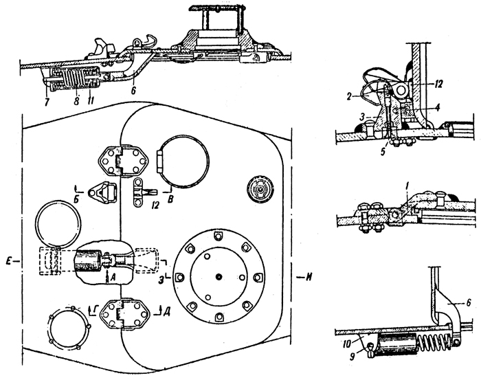
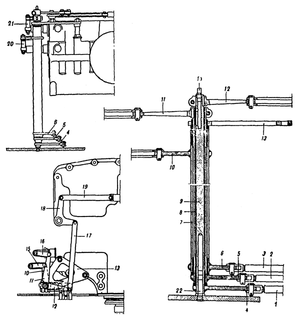
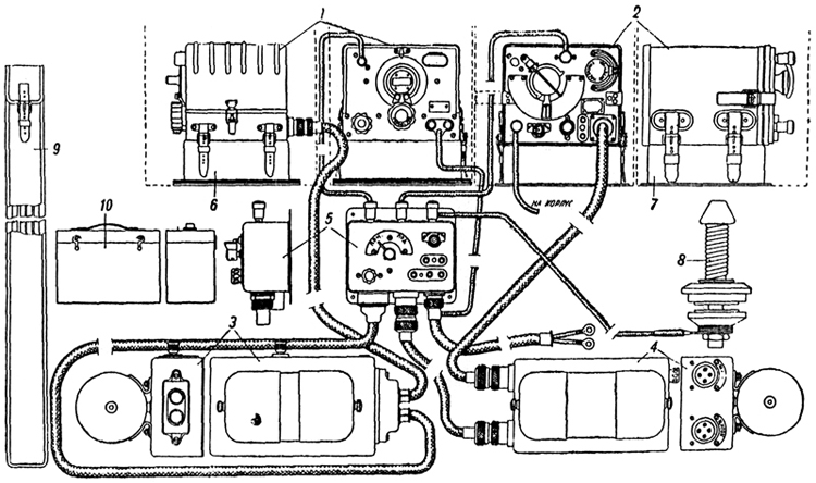
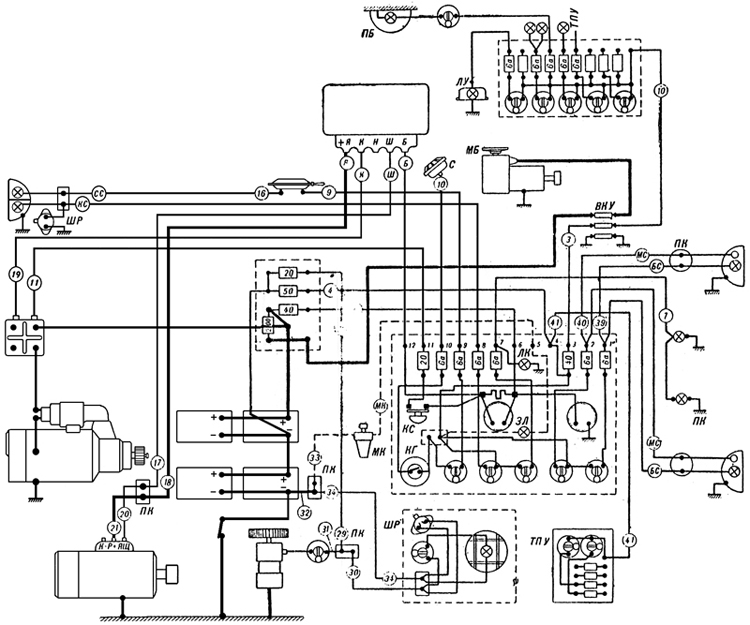
Plate 50 - Electrical Layout Of Tank ��3"ii�_#1
- Turret traverse motor - Horn - Transfer box - Horn button - Starter button - Green lamp - Oil cock - Plug-in rosette - Lamp illuminating clinometer - Turret roof - Lamp illuminating panel h�s�
5a�IJ
(The strength of the current is indicated on the fuses. The figure in circles on the leads indicate the number of the lead. The number on leads from the turret panel have terminal numbers except Nos. 39, 40, 41. If each end of a lead has a different designation then both designations will be in the circle). -�'iV-��]<
The electrical system of the tank consists of two circuits, one of 24V for the starter and turret traverse motor and the other 12 V for the remaining components. �R8�U�?s/*
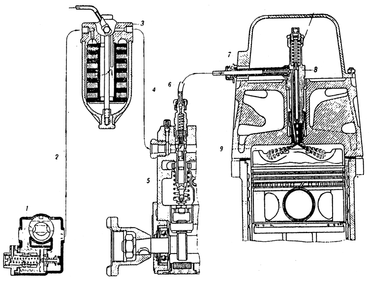
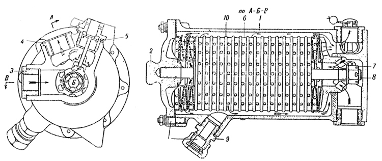
The Generator 4563/A and the Voltage Regulator PPT 4576/A =5�jn�g�.�
The generator consists of a 24V shunt dynamo. The generator is mounted on the right side of the engine and is fastened by two securing bands. It is driven by the engine through a slipping clutch. The maximum capacity of the generator is 1 kilowatt. &n)=OConge
The accumulators begin to be charged when the crankshaft reaches a speed of 600-650 rpm. ��mlmp��'f
On the body of the generator there are three terminals "+R" , "K-p" and "+h". (ed: note these figures in quotes are barely legible and may be incorrect) "+R" is the positive terminal. ^k7`:@
z0U
The generator works simultaneously with the voltage regulator which is mounted in the left instrument panel. wZ_k��]�{J
The voltage regulator consists of three controls: the cut-out, current limiter and voltage regulator. .��+ w#�n<
The cut-out has the following purposes: Z�*�Fxr;)d
1. To engage the generator automatically when owing to increasing revs, its voltage becomes higher than that of the accumulators (25 to 27 volts). 3h-C&��C��
2. For the automatic disengagement of the generator when its voltage is less than the voltage of the accumulators. �R!8�qk�G�
The voltage regulator maintains the voltage of the generator constant in spite of the changing engine revs. The constant current depends on the load. with loads of 30 Amps the voltage is 25 V. and travelling on the level at is 30-32V. ���Rt^�~db
The current limiter limits the current from the generator to within 38-42 amps. w`"��)^KXi
 LyB &u�(�) LyB &u�(�)
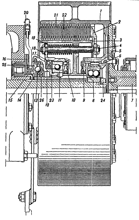
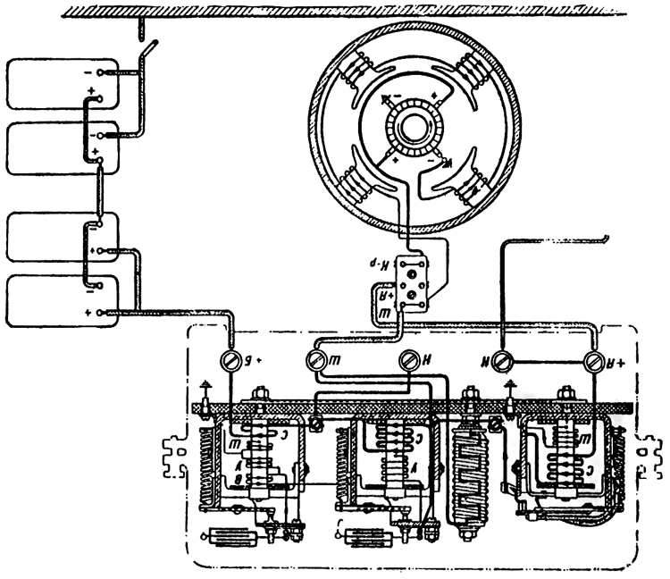
Plate 51 - Lay-out of coils of Voltage Regulator PPT 4576/A E 9L�KVs}�
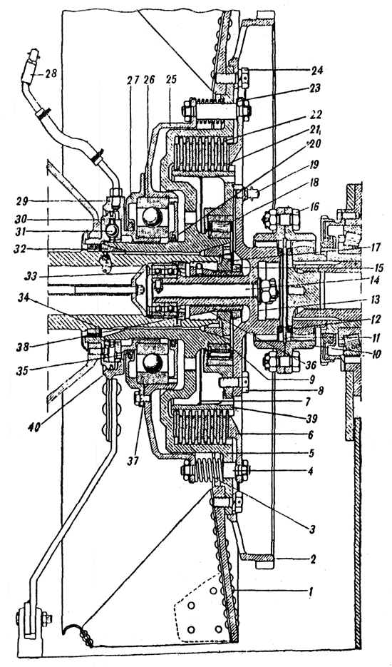
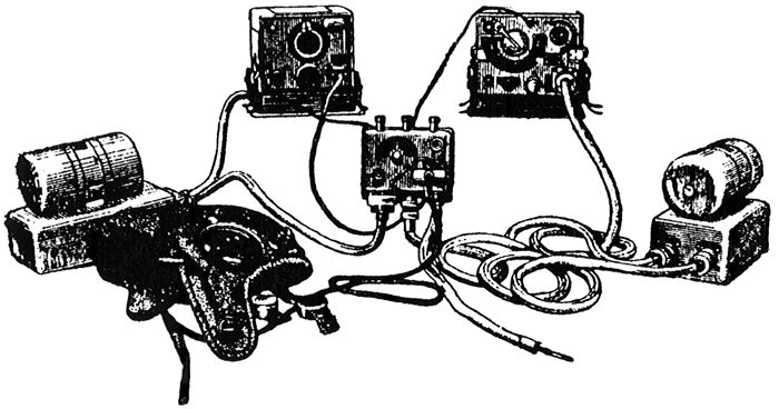
The connection between the generator and the voltage regulator (Plate 51 ) From the terminal "+R" of the generator, the current travels to the lower terminal of the junction box on the right engine block and thence to the terminal "+R" of the voltage regulator. From the voltage regulator the current goes from the terminal "W" to the upper terminal "W" of the generator. From the terminal "5" of the voltage regulator the current travels to the terminal No.12 of the driver's switch panel, the ammeter and through terminal No. 6 across the fuse-box and fuse (4Oa) into the accumulator. ��N��hnw'9
INSTRUCTIONS F0R REMOVING THE ACCOMULATORS. Y�"�RjMyQh
1. Switch off the earth switch. L6-��zQztn
2. Remove the ammunition stored in the engine bulkhead. �a*�4l!-�7
3. Open the doors of the engine bulkhead. wN�X�2* ��
4. Unscrew the negative terminal of the right front accumulator. Disconnect the bridge connecting the right and left group of accumulators. Disconnect the terminals of the left front accumulators. 'nO%1BZj+�
5. Unscrew the nuts and remove the clamp holding the front accumulators. `X06JTqf�:
6. Remove the front accumulators and take out the central securing board of the baskets of the front and rear accumulators. b�m+�
#�OI
7. Remove the rear accumulators. l�&�f"�qF?
To replace the accumulators the reverse order applies. 18x�T2�f��
To connect the earth switch it is necessary to strike its head with the palm of the hand and press the knob at the side of the switch. "`jey)&H*M
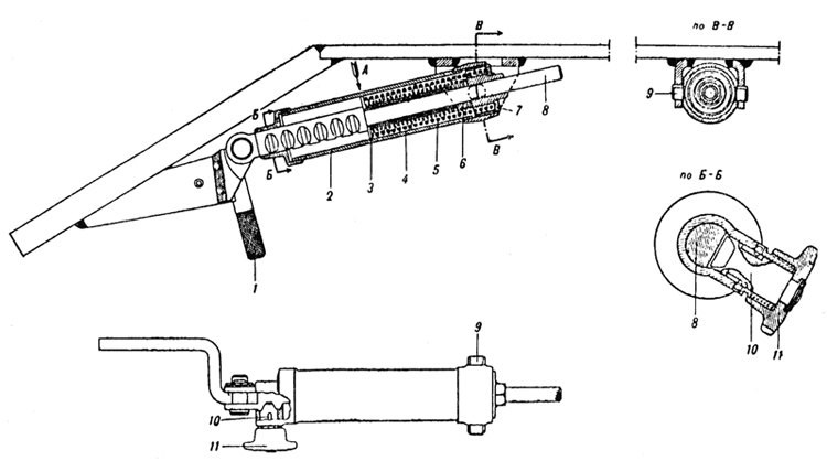
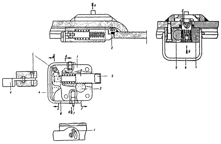
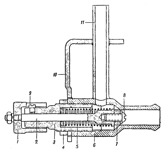
CT- 700 STARTER B�]o5�HA<k
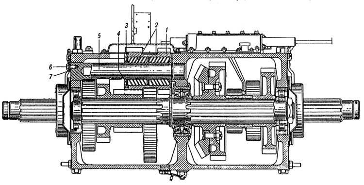
The starter is mounted on a special platform on the gearbox with its starting relay to the right. ���ta\C�Zp
It is a 24 volt starter motor of 15 h.p. and consists of the following main parts: electric motor, control coupling, control relay, and starting relay. "�D��ni�DA
The principal part of the starter is the series motor. /��d\#�|[S
The control coupling slides on the splined shaft of the starter and consists of the starter gear and a multiplate clutch. A double shouldered forked lever moving on a shaft causes the coupling to be moved horizontally along the shaft thus engaging the toothed ring on the flywheel with the starter gear. For disengaging the coupling a return spring is provided on the shaft of the lever. Jbrjt/OG#I
The action of the sliding coupling is as follows: by rotating the armature, the coupling transmits from the shaft to the starter gear and beyond to the toothed ring of the flywheel then the engine picks up and begins to turn at a greater number of revs than the starter motor, the sliding coupling disengages leaving the armature to revolve on its own. This protects the starter from damage.
���d/fg�
The control relay PCT-334 is fixed to the starter. It has the following tasks : nYc8+5CcK'
1. To engage the starter with the toothed ring �~r�W�y�s=
2. When the gear is in mesh with the starter ring, to transmit current to the motor �)_\Z�Uem�
The starting relay of the starter PC-371 and PC-400 serves to transmit the current to the starter when the button is pressed and to cut-out automatically the current after the engine is started. The starting relay consists of a powerful electromagnet and a contact system. '%2q'
LqSA
Testing the conditions of the accumulators �X�DW��R�]
On connecting the earth switch the voltmeter should read 24-25 volts. A smaller voltage evidences a discharge. �NQx`u"�=�
When the accumulators are properly charged the charging unit should be 14-16 amps. When the engine is running at 900 rpm or more. With discharged batteries the current reaches 30 amps. The accumulators must be charged if the current reaches 20-22 amps. 3{wmKo|_�X
The condition of the accumulators can be tested on the voltmeter by turning the engine round for three to five seconds without fuel by means of the starter. 5��A~lu4-q
With correct and charged accumulators the voltage must not be less than 17-18 volts. If less, then it is clear that there is either a fault or the accumulators are discharging. FX�i"o
�$N
With a cold engine in winter it is necessary to test the accumulators in this way since a fall in voltage is considerably greater with faulty and discharged accumulators. uFzvb0O`O
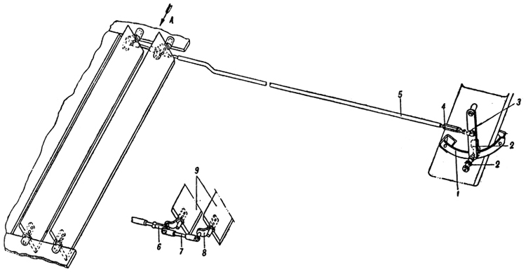
The earth switch comprises a switch across the negative poles of the batteries which connects to the hull of the tank. It is situated on the right side of the tank at the right side of the wireless operator. p�h;ds+b
�
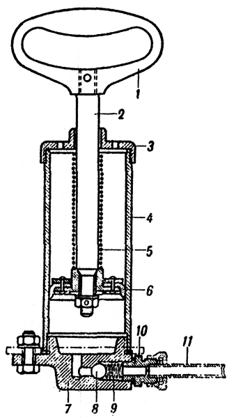
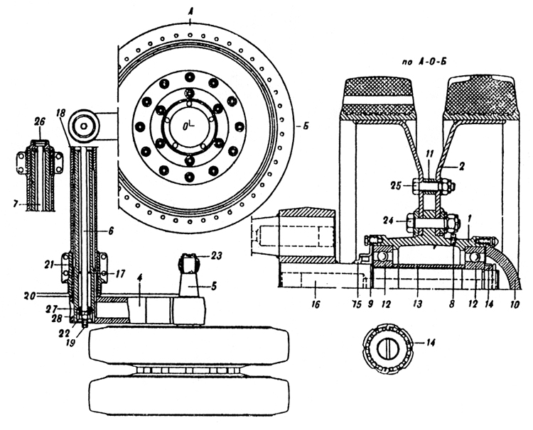
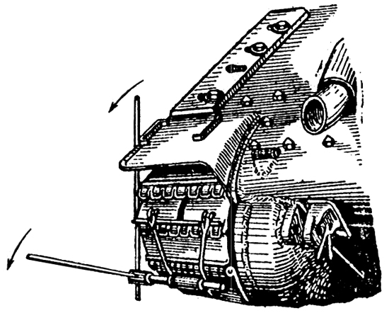
Installing the Starter in the Tank �%x�q/eC7
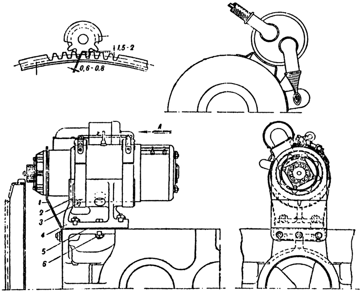
The starter is mounted on the bracket 4 on the gearbox. mjwh40x.�o
When installing the starter it is necessary to leave a clearance between the end of the gearwheel and the stater ring of 4 to 4.5 mm. \
�LQ?s)�~
This clearance should be measured with a feeler gauge. The starter should be adjusted for height so that the clearance between the teeth of the gear wheel and the starter ring is 0.6-0.3 mm. This clearance is adjusted by the packing washers 5 between the bracket and the gearbox. �TN�HkHR[&
 hrRkam��!y hrRkam��!y
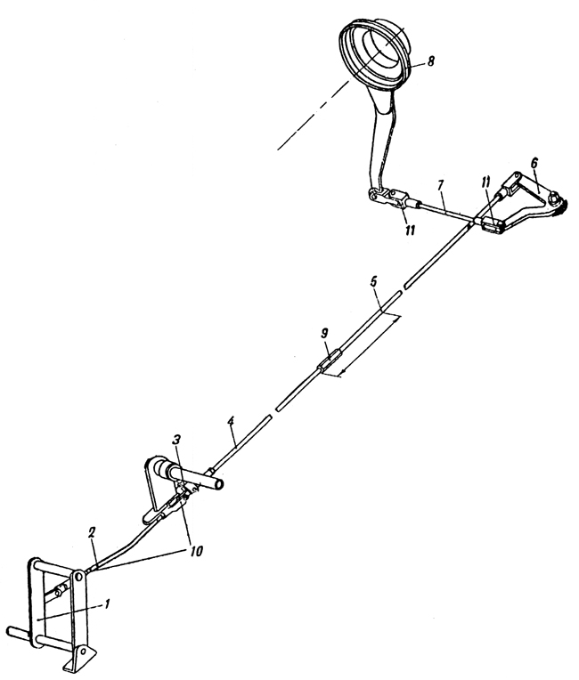
Plate 52 - Starter CT-700 EqV]/0-��\
1. Supporting bracket lLb">�<8�a
2. Securing strap X�4"�D Lt"
3. Assembly pin ,a�&&y0�,�
4. Bracket |H L�U�5=Y
5. Packing t[� Z�oe+&
6. Fitted bolt ]26
Q*.1~�
Maintenance of the starter CSC
sJE#4�
1. Inspect the commutator and brushes once a month. #BK�3CD(�&
2. After every 50 working hours, remove the front cap of the starting relay and examine the contacts. >�*hY�1@N1
Lubrication ^s_�B�Y+�#
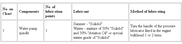
Every 12-15 engine working hours the lubricator at the side of the control should be filled with 15 to 20 drops of "Avia" oil and, having removed the cap of the bearing at the side of the commutator, pack the bearing with grease (Konstalin or Solidol). ��r�L�U+-_
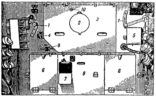
DRIVER'S SWITCH PANEL �$T)
E�Je�
This panel is situated at the left of the driver and contains the ammeter and voltmeter. The general arrangement of the panel is shown in Plate 50. �g=T
�!fF=
The front headlight serves to illuminate the road at night and has two lamps one of greater brilliance than the other. The brighter light is marked (something I can't make out). The smaller lamp is operated by the switch marked "M CneT" cM= ?�{W7~
The tail light has two lamps one behind a blue glass and one behind a red glass. The upper blue light is operated on application of the brakes which causes the contacts of the "Stop" switch to be closed. Z�T�\=:X*e
The Horn rø 4702 is of the vibrator type. bh9!�OqK9K
The electric fan MB12 is for ventilation of the fighting compartment. X
��\�1grM
Inspection lamp is mounted in the right front corner of the fighting compartment and can be used for illuminating the fighting compartment. It is portable and can be used when the earth is switched off. 9�F
&s9(=\
Current supply panel for wireless and intercom is situated inside the glacis plate at the left of the wireless operator. It is connected to the terminal 4 on the main switch panel. EPE9�
Hv�N
ELECTRICAL EQUIPMENT OF THE TURRET 9Hj�tW�Q�n
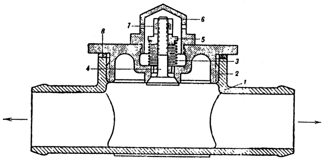
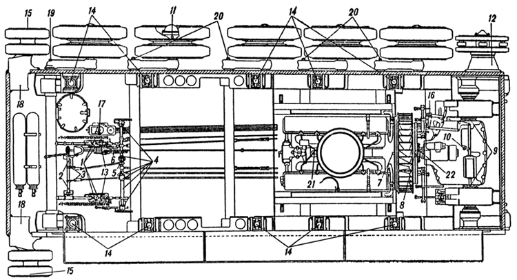
The rotary base junction (BKy) is situated on the floor of the tank in the middle of the fighting compartment. B`Q~p��92�
Inside the rotary base junction there is a system of insulated rings - three high tension and six low tension. The rings rotate with the turret and around them there are brushes which are fixed to the body of the rotary base junction. HX(Z��(rcI
Leads going to the tank are fixed to the bushes, and leads going to the turret from the rings. Through the lower No.1 ring the earth of the turret is connected, to the earth of the tank. Through the middle ring No. 2 +12V is transmitted to the turret, and through the upper ring No. 3 +24 volts is transmitted to the turret. The low tension rings are used for the intercom. �
d�1"�%sI
Turret traversing mechanism (Mb-20) has a capacity of 1350 watts, the maximum number of (something) per minute on the voltage 20V. The motor is controlled by the traversing handwheel and rheostat mounted on the motor. By turning the handwheel to the right, the turret is traversed to the right and by turning the handwheel to the left, the turret is traversed to the left. &ZmHR^Flz�
The handwheel is locked automatically in the neutral position by the knob. t�=Ip�V�l!
The rheostat handwheel has three positions at each side corresponding to three speeds. When using the motor the third or highest speed must always be used, as prolonged use of the rheostat causes it to overheat and burn. n%M-L[�n�
PARTICULARS OF THE ELECTRIC EQUIPMENT OF THE TANK U��49#?�^?
1. It is necessary to dis-coru1oct the earth system then the engine is working otherwise the 12 volt components will burn. �x�Ty[X"sJ
2. By disconnecting the earth switch and switching on any component (except the inspection lamp) the voltmeter will indicate a voltage of 12 V. �nsRZy0@$t
3. The ammeter indicates the effective charging current of both groups of batteries only then the load is switched on. H�Fr�#Ql>g
4. On disconnecting the earth switch and connecting the traversing motor all the 12 volt users will work, supplied with current from the left group of batteries (except the inspection lamp). ]W��-�7 U_
BASIC RULES FOR THE ELECTRIC EQUIPMENT �Vh��W�F(*
1. During maintenance, disconnect the earth switch. X~`<�ik{q
2. Then working in the Transmission compartment, the earth switch must be on. y�t�+"�\d�
3. The terminal nuts on the batteries should be kept firmly screwed down and oxidisation should not be allowed to form. �iL%Q�@!ka
Table of Faults in Electrical Circuit of Tank l Wa4X#�~.
Fault Cause Means of Correcting Fault 'D�B4po. �
1. Absence of current on the instrument panel, horn does not work, headlights and lamp not working but the voltmeter shows a voltage and starter works. Earth switched on a) Fuse No. 50 in the fuse box burnt out. Y�0�f
"}A1
b) Loose connection between the fuse box and terminal 4 on the panel. �01 ��vE�t
a) Replace z�O)�>(�E?
b) Test terminal nuts, replace lead ��/n
�9�yv
2. On pressing the starter button, the starting relay works, and the starter is switched on but is not strong enough to turn the engine round. The voltage falls below 17V. ��LZ97nvK�
a) Discharged or faulty accumulators �Od�?M4Ed(
b) Extremely cold accumulators (in winter) �ubpVrvu@�
c) Loose high tension lead from the accumulators to the fuse box and to the earth switch a<W[???m/M
a) Replace /ynvQ1#uA�
b) Place the accumulators in a warm place �o�]#M8)=�
c) Tighten terminals -t<8)9q�(�
3. The starter works but the engine is not turned over. a) Starter clutch slipping a) Remove starter and hand over to artificer for adjusting the coupling 5L'b
�F2SI
4. After the engine has started, the starter gear does not disengage. a) Short circuit starter relay coil (leaked to earth) Vz���"J��a
b) Sooting up of the contacts in the starting relay ^X&n�-ui
�
c) Seizing up of the coupling control on the shaft of the starter Bbb_}y|CA�
a) Replace the relay @bc=O1vX~;
b) Replace the relay 5iG+O�4n�%
c) Remove the starter and hand over to artificer 0n��h;��0Z
In all cases of the starter not disengaging, quickly stop the engine and switch off earth switch. �zSpL�^:�~
5. The ammeter does not indicate the charging current. a) Fuse 40 in the fuse box burnt out A �11w{`EM
b) Breakage or slackening of the contacts in the circuit connecting generator, voltage regulator and fuse box qM.�"W=XVN
c) Generator is not charging a) Replace the fuse +, SU���J|
b) Test the following terminals for tightness: generator junction box, "+R", "M" and "B" on the voltage regulator " " on the panel and the leads 12, 17, 18. M7�\;� �Y�
c) Remove and replace �j"8�f,e�r
Test the connections of leads 20 and 21 from the terminals on the generator Junction box. Connect them across the lamp tester to earth. At an engine speed of 600-700 rpm the lamp should burn brightly in the case of a faultless generator. �W'
DpI�7�
6. Voltmeter does not show a reading, the starter functions and the ammeter shows a current. 4!��Cu>�8B
a) Voltmeter defective zjzW;bo( d
b) The bridge connecting the panel to earth is disconnected A[�/_�}bI|
a) Call out the electrician for replacement F)W7,^=X>-
b) Tighten connections J�73�B$0FP
7. The turret traversing motor not working. _�o
2py�V&
a) Fuse 200 in the fuse box burnt out (&=<UGY�(w
b) Terminals loose �cW�d�\�Ki
c) Rotary base Junction disconnected or its brushes connecting poorly ��&�I&:��
d) Faulty motor Ly?%RmH��K
a) Replace �"�1<>c�/h
b) Test and tighten i|@�l�UXBp
c) Test and correct faults A�j�TkQ�)
d) Remove engine and hand over for repair |