«1 2 » Pages: ( 2/2 total )
本页主题: 【挖坑翻译】T-34/76 苏联红军战术手册 苏联国防人民委员会颁发1942 莫斯科 打印 | 加为IE收藏 | 复制链接 | 收藏主题 | 上一主题 | 下一主题

vonreynard
匈牙利人民共和国国民议会主席团主席
第一次社会主义劳动英雄称号 十月革命勋章 第一枚劳动红旗勋章
级别: 贵宾/顾问/元老


精华: 2
发帖: 1011
爱心: 1011 点
金钱: 10400 卢布
好评度: 0 点
国籍门派: 匈牙利人民共和国
在线时间:649(小时)
注册时间:2007-11-23
最后登录:2011-07-21


Chapter V. ELECTRICAL EQUIPMENT OF THE TANK
(Please note: due to the large number of cryillic characters in this section, I have used the closest Latin characters to make converting this section easier) 0|j44e }  
The electrical equipment of the tank consists of: eZ[Qhrc  
1. Generator and four accumulators. j$/#2%OVN  
2. Starter motor, turret traversing motor, electric fan, interior and exterior lighting, horn, wireless set and intercommunication system. Db*b"/]  
3. Driver's switch panel, turret switch panel, rotary base junction and earth switch. 4^:dmeMZ`  
$|J+  
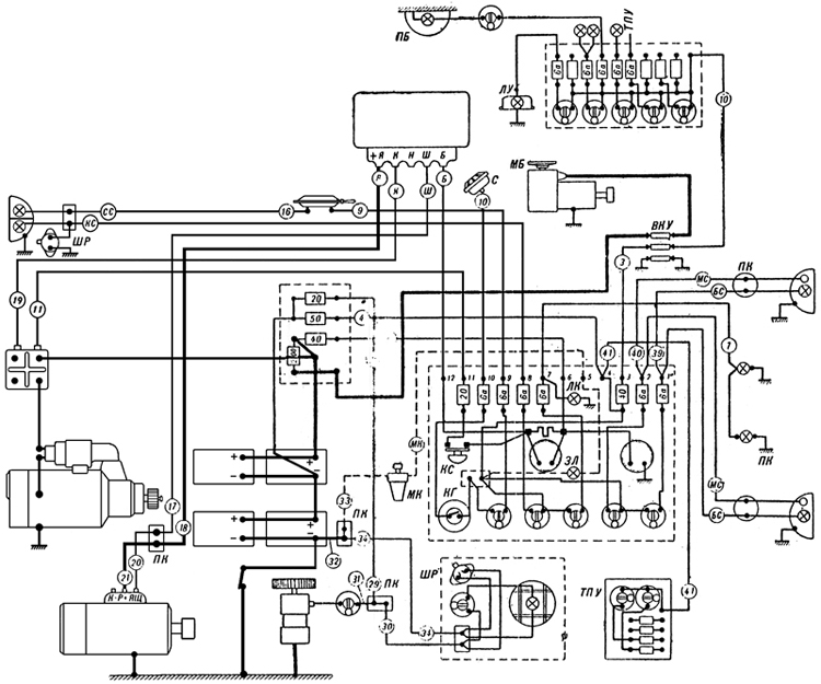
Plate 50 - Electrical Layout Of Tank e Ru5/y~  
- Turret traverse motor - Horn - Transfer box - Horn button - Starter button - Green lamp - Oil cock - Plug-in rosette - Lamp illuminating clinometer - Turret roof - Lamp illuminating panel AA=rjB9  
(The strength of the current is indicated on the fuses. The figure in circles on the leads indicate the number of the lead. The number on leads from the turret panel have terminal numbers except Nos. 39, 40, 41. If each end of a lead has a different designation then both designations will be in the circle). 7#G!es  
The electrical system of the tank consists of two circuits, one of 24V for the starter and turret traverse motor and the other 12 V for the remaining components. u pUJF`3  
The Generator 4563/A and the Voltage Regulator PPT 4576/A glU9A39qx?  
The generator consists of a 24V shunt dynamo. The generator is mounted on the right side of the engine and is fastened by two securing bands. It is driven by the engine through a slipping clutch. The maximum capacity of the generator is 1 kilowatt. 0uW)&>W  
The accumulators begin to be charged when the crankshaft reaches a speed of 600-650 rpm. O#18a,o@  
On the body of the generator there are three terminals "+R" , "K-p" and "+h". (ed: note these figures in quotes are barely legible and may be incorrect) "+R" is the positive terminal. '/Hoq  
The generator works simultaneously with the voltage regulator which is mounted in the left instrument panel. }s@IQay+  
The voltage regulator consists of three controls: the cut-out, current limiter and voltage regulator. WoGnJ0N q  
The cut-out has the following purposes: (GL'm[V  
1. To engage the generator automatically when owing to increasing revs, its voltage becomes higher than that of the accumulators (25 to 27 volts). ?Sa,n^b*H  
2. For the automatic disengagement of the generator when its voltage is less than the voltage of the accumulators. KGo^>us  
The voltage regulator maintains the voltage of the generator constant in spite of the changing engine revs. The constant current depends on the load. with loads of 30 Amps the voltage is 25 V. and travelling on the level at is 30-32V. C R?}*  
The current limiter limits the current from the generator to within 38-42 amps. +6jGU '}[  
.JB1#&B +  
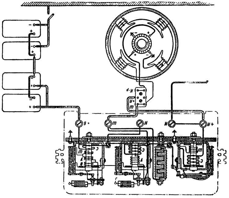
Plate 51 - Lay-out of coils of Voltage Regulator PPT 4576/A wXqwb|2  
The connection between the generator and the voltage regulator (Plate 51 ) From the terminal "+R" of the generator, the current travels to the lower terminal of the junction box on the right engine block and thence to the terminal "+R" of the voltage regulator. From the voltage regulator the current goes from the terminal "W" to the upper terminal "W" of the generator. From the terminal "5" of the voltage regulator the current travels to the terminal No.12 of the driver's switch panel, the ammeter and through terminal No. 6 across the fuse-box and fuse (4Oa) into the accumulator. Ij.mLO]  
INSTRUCTIONS F0R REMOVING THE ACCOMULATORS. <X4f2z{T{@  
1. Switch off the earth switch. YzM/?enK}T  
2. Remove the ammunition stored in the engine bulkhead. xZ`vcS(  
3. Open the doors of the engine bulkhead. W5Pur lu?  
4. Unscrew the negative terminal of the right front accumulator. Disconnect the bridge connecting the right and left group of accumulators. Disconnect the terminals of the left front accumulators. ip}%Y6Wj  
5. Unscrew the nuts and remove the clamp holding the front accumulators. >yP> ]r+  
6. Remove the front accumulators and take out the central securing board of the baskets of the front and rear accumulators. &-Wt!X 3  
7. Remove the rear accumulators. ':_gYA  
To replace the accumulators the reverse order applies. O|=?!|`o  
To connect the earth switch it is necessary to strike its head with the palm of the hand and press the knob at the side of the switch. mk!8>XvM  
CT- 700 STARTER j?]+~  
The starter is mounted on a special platform on the gearbox with its starting relay to the right. uE(5q!/  
It is a 24 volt starter motor of 15 h.p. and consists of the following main parts: electric motor, control coupling, control relay, and starting relay. 0n`Temb/  
The principal part of the starter is the series motor. a*D<J}xe  
The control coupling slides on the splined shaft of the starter and consists of the starter gear and a multiplate clutch. A double shouldered forked lever moving on a shaft causes the coupling to be moved horizontally along the shaft thus engaging the toothed ring on the flywheel with the starter gear. For disengaging the coupling a return spring is provided on the shaft of the lever. Q$]1juqg  
The action of the sliding coupling is as follows: by rotating the armature, the coupling transmits from the shaft to the starter gear and beyond to the toothed ring of the flywheel then the engine picks up and begins to turn at a greater number of revs than the starter motor, the sliding coupling disengages leaving the armature to revolve on its own. This protects the starter from damage. <D)@;A  
The control relay PCT-334 is fixed to the starter. It has the following tasks : t g-(e=S4P  
1. To engage the starter with the toothed ring 85[ 7lO)[  
2. When the gear is in mesh with the starter ring, to transmit current to the motor ',WJ'g  
The starting relay of the starter PC-371 and PC-400 serves to transmit the current to the starter when the button is pressed and to cut-out automatically the current after the engine is started. The starting relay consists of a powerful electromagnet and a contact system. +4T.3Njjn  
Testing the conditions of the accumulators Ank_;jo  
On connecting the earth switch the voltmeter should read 24-25 volts. A smaller voltage evidences a discharge. &K9RV4M5  
When the accumulators are properly charged the charging unit should be 14-16 amps. When the engine is running at 900 rpm or more. With discharged batteries the current reaches 30 amps. The accumulators must be charged if the current reaches 20-22 amps. Vn{;8hZ :a  
The condition of the accumulators can be tested on the voltmeter by turning the engine round for three to five seconds without fuel by means of the starter. kv2o.q  
With correct and charged accumulators the voltage must not be less than 17-18 volts. If less, then it is clear that there is either a fault or the accumulators are discharging. {v=[~H>bt  
With a cold engine in winter it is necessary to test the accumulators in this way since a fall in voltage is considerably greater with faulty and discharged accumulators. !]A/ID0K  
The earth switch comprises a switch across the negative poles of the batteries which connects to the hull of the tank. It is situated on the right side of the tank at the right side of the wireless operator. \I4Uj.'> \  
Installing the Starter in the Tank V( 0Y   
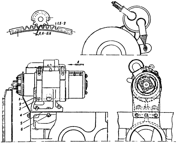
The starter is mounted on the bracket 4 on the gearbox. ^mFsrw  
When installing the starter it is necessary to leave a clearance between the end of the gearwheel and the stater ring of 4 to 4.5 mm. g4Dck4^!4  
This clearance should be measured with a feeler gauge. The starter should be adjusted for height so that the clearance between the teeth of the gear wheel and the starter ring is 0.6-0.3 mm. This clearance is adjusted by the packing washers 5 between the bracket and the gearbox. G9QvIXRi  
.-& =\}^2l  
Plate 52 - Starter CT-700 _eBNbO_J  
1. Supporting bracket PHI c7*_  
2. Securing strap ps,Kj3^T<  
3. Assembly pin R[v<mo[s  
4. Bracket ;'V[8`Z@  
5. Packing t B`"gC~  
6. Fitted bolt 0Qvr g+  
Maintenance of the starter i>CR{q  
1. Inspect the commutator and brushes once a month. <b _K*]Z  
2. After every 50 working hours, remove the front cap of the starting relay and examine the contacts. ^ /%Y]d$  
Lubrication !.O[@A\.-  
Every 12-15 engine working hours the lubricator at the side of the control should be filled with 15 to 20 drops of "Avia" oil and, having removed the cap of the bearing at the side of the commutator, pack the bearing with grease (Konstalin or Solidol). ,%xat`d3,3  
DRIVER'S SWITCH PANEL 7]5~ml3:  
This panel is situated at the left of the driver and contains the ammeter and voltmeter. The general arrangement of the panel is shown in Plate 50. J>#yA0QD2  
The front headlight serves to illuminate the road at night and has two lamps one of greater brilliance than the other. The brighter light is marked (something I can't make out). The smaller lamp is operated by the switch marked "M CneT" @g;DA)!(  
The tail light has two lamps one behind a blue glass and one behind a red glass. The upper blue light is operated on application of the brakes which causes the contacts of the "Stop" switch to be closed. u #}1 M  
The Horn rø 4702 is of the vibrator type. _4SZ9yu  
The electric fan MB12 is for ventilation of the fighting compartment. s91[DT4  
Inspection lamp is mounted in the right front corner of the fighting compartment and can be used for illuminating the fighting compartment. It is portable and can be used when the earth is switched off. v*JKLA  
Current supply panel for wireless and intercom is situated inside the glacis plate at the left of the wireless operator. It is connected to the terminal 4 on the main switch panel. u^E0u^  
ELECTRICAL EQUIPMENT OF THE TURRET Rc4=zimr+  
The rotary base junction (BKy) is situated on the floor of the tank in the middle of the fighting compartment. ,Fkq/h  
Inside the rotary base junction there is a system of insulated rings - three high tension and six low tension. The rings rotate with the turret and around them there are brushes which are fixed to the body of the rotary base junction. d#bg(y\G|  
Leads going to the tank are fixed to the bushes, and leads going to the turret from the rings. Through the lower No.1 ring the earth of the turret is connected, to the earth of the tank. Through the middle ring No. 2 +12V is transmitted to the turret, and through the upper ring No. 3 +24 volts is transmitted to the turret. The low tension rings are used for the intercom. Ph.RWy")  
Turret traversing mechanism (Mb-20) has a capacity of 1350 watts, the maximum number of (something) per minute on the voltage 20V. The motor is controlled by the traversing handwheel and rheostat mounted on the motor. By turning the handwheel to the right, the turret is traversed to the right and by turning the handwheel to the left, the turret is traversed to the left. Z+);}>-5  
The handwheel is locked automatically in the neutral position by the knob. 7p':a)  
The rheostat handwheel has three positions at each side corresponding to three speeds. When using the motor the third or highest speed must always be used, as prolonged use of the rheostat causes it to overheat and burn. %'e$N9zd  
PARTICULARS OF THE ELECTRIC EQUIPMENT OF THE TANK 'sa)_?Hy  
1. It is necessary to dis-coru1oct the earth system then the engine is working otherwise the 12 volt components will burn. mSu$1m8  
2. By disconnecting the earth switch and switching on any component (except the inspection lamp) the voltmeter will indicate a voltage of 12 V. x$TL j  
3. The ammeter indicates the effective charging current of both groups of batteries only then the load is switched on. *)^ ZUk  
4. On disconnecting the earth switch and connecting the traversing motor all the 12 volt users will work, supplied with current from the left group of batteries (except the inspection lamp). s}` |!Vyl  
BASIC RULES FOR THE ELECTRIC EQUIPMENT g +gcH  
1. During maintenance, disconnect the earth switch. { 6qxg_{  
2. Then working in the Transmission compartment, the earth switch must be on. 3PRU  
3. The terminal nuts on the batteries should be kept firmly screwed down and oxidisation should not be allowed to form. aCQ[Uc<B:  
Table of Faults in Electrical Circuit of Tank 9 4lt?|3=  
Fault Cause Means of Correcting Fault S\t!7Xs%*U  
1. Absence of current on the instrument panel, horn does not work, headlights and lamp not working but the voltmeter shows a voltage and starter works. Earth switched on a) Fuse No. 50 in the fuse box burnt out. )c9Xp:  
b) Loose connection between the fuse box and terminal 4 on the panel. <'sm($.2  
a) Replace L1Yj9i  
b) Test terminal nuts, replace lead >Jn`RsuV  
2. On pressing the starter button, the starting relay works, and the starter is switched on but is not strong enough to turn the engine round. The voltage falls below 17V. !J<0.nO/:  
a) Discharged or faulty accumulators =X[?d/[  
b) Extremely cold accumulators (in winter) "10\y{`v^  
c) Loose high tension lead from the accumulators to the fuse box and to the earth switch b 1Wz  
a) Replace s!D2s2b9e  
b) Place the accumulators in a warm place UCj+V@{  
c) Tighten terminals T8&sPt,f  
3. The starter works but the engine is not turned over. a) Starter clutch slipping a) Remove starter and hand over to artificer for adjusting the coupling R N@)nc_  
4. After the engine has started, the starter gear does not disengage. a) Short circuit starter relay coil (leaked to earth) m3P7*S5NJ7  
b) Sooting up of the contacts in the starting relay Xg_l4!T_l  
c) Seizing up of the coupling control on the shaft of the starter M3]eqxLC  
a) Replace the relay IV':sNV  
b) Replace the relay w?nSQBz$  
c) Remove the starter and hand over to artificer &{a#8sbf#c  
In all cases of the starter not disengaging, quickly stop the engine and switch off earth switch. X_D-K F  
5. The ammeter does not indicate the charging current. a) Fuse 40 in the fuse box burnt out G@jx&#v  
b) Breakage or slackening of the contacts in the circuit connecting generator, voltage regulator and fuse box Xf7]+  
c) Generator is not charging a) Replace the fuse 06.8m;{N  
b) Test the following terminals for tightness: generator junction box, "+R", "M" and "B" on the voltage regulator " " on the panel and the leads 12, 17, 18. 30Qp:_D  
c) Remove and replace OT|0_d?bD  
Test the connections of leads 20 and 21 from the terminals on the generator Junction box. Connect them across the lamp tester to earth. At an engine speed of 600-700 rpm the lamp should burn brightly in the case of a faultless generator. ]K>bSK^TX  
6. Voltmeter does not show a reading, the starter functions and the ammeter shows a current. pMViq0  
a) Voltmeter defective  Q$`uZ  
b) The bridge connecting the panel to earth is disconnected [U^Cz{G  
a) Call out the electrician for replacement #sjGju"#_  
b) Tighten connections MzKl=G  
7. The turret traversing motor not working. b|kL*{;  
a) Fuse 200 in the fuse box burnt out 4o@:+T:1  
b) Terminals loose |G6'GTwZD  
c) Rotary base Junction disconnected or its brushes connecting poorly i-4L{T\K  
d) Faulty motor I D-I<Ev  
a) Replace a+k3wzJ  
b) Test and tighten lAC "7 Z?F  
c) Test and correct faults Y|hd!C-x  
d) Remove engine and hand over for repair
享生一世澜陨阔
斯年寸草何足灼
留待后世话今昔
烈风细雨笑声谈
顶端 Posted: 2008-09-09 12:20 | 10 楼
vonreynard
匈牙利人民共和国国民议会主席团主席
第一次社会主义劳动英雄称号 十月革命勋章 第一枚劳动红旗勋章
级别: 贵宾/顾问/元老


精华: 2
发帖: 1011
爱心: 1011 点
金钱: 10400 卢布
好评度: 0 点
国籍门派: 匈牙利人民共和国
在线时间:649(小时)
注册时间:2007-11-23
最后登录:2011-07-21


Chapter VI. GENERAL CONSTRUCTION AND EMPLOYMENT OF THE WIRELESS SET 9-P
(Please note: due to the large number of cryillic characters in this section, I have used the closest Latin characters to make converting this section easier) pbWjTI$  
General Description (Plate 54) jt*B0'Sa  
The purpose of the wireless set 9-P is for maintaining radio telephonic communication between the tank section and the separate tanks. a gL@A  
The rod aerial is 4 metres high. ^4<&"aoo  
The frequency of the transmitter is 4050 to 5625 kg.cy (??Hz??) (74 to 53.3 meters). mC(YO y  
The range of the set is 18 km on the move and 25 km when stationary. >$ro\/  
The Wireless set is designed to work with the intercom sets Tny 3 and Tny 4 BNC. The current supply for the set comes from the 12V circuit and the current supply for the intercom from the transformer -10. h>!9N dzG  
A =&`TfXu  
Plate 54 - Wireless installation 9-P M&9urOa`  
1. Receiver mWn0"1C  
2. Transmitter }:J-o  
3. PYH-10 Transformer with filter wPcEvGBN=  
4. PYH-30 Transformer with filter r/P}j4)b7  
5. Panel 6. Shock-absorbing pad of receiver q68m*1?y  
7. Shock-absorbing pad for 'transformer %CgV:.,K  
8. Aerial holder }&6:0l$4!  
9. Case for rod aerial d:_;  
10. Spares box. %AWc`D  
Main Parts of Wireless Set (Plate 55) fuF{8-ua  
1. Transmitter with shock-absorbing pad. ;/+U.I%z  
2. Receiver with shock-absorbing pad. ]TcQGW@'  
3. Transformer PyH-30 with filter. QX=x^(M$m  
4. Transformer PyH-10 with filter and two cables leading to panels and to receiver. U. $Th_  
5. Control panel with feed cable (connecting the 12V circuit) and with telephonic flex (to receiver). -m ;n}ECg  
6. Headset with accessories (telephones, throat microphone, flex with forked plug}. :c8d([)$  
7. Cable connecting the feed plug of the transmitter to the left hand plug of the transformer PyH-30. # M!1W5#  
8. Cable connecting the middle plug of the panel to the right plug of the transformer PyH-30. itc\wn  
9. Aerial assembly consisting principally of a shock absorber and four equal lengths of rod. ,]n~j-X  
10. Box of spare parts. 6P,uy;PJ  
44YKS>Cq  
Plate 55 - Wireless Set 9-P p_EM/jI,  
Inspection, Testing and Preparation of the Set `YMd0*  
Before using the wireless set it must be tested and prepared. =WZ@{z9J  
The main parts of the wireless set as described above must be checked over separately and afterwards the set should be prepared in the following order :- a <F2]H=J  
1. Fit the rod aerial and at the same time test its joints for tightness also test the terminals and leads to the transmitter and receiver for tightness and insulation. GWWaH+F[h  
2. Inspect the aerial insulator and clean off mud and dust. e VQ-?DK  
3. Test for tightness the terminals of the leads from the aerial to the terminal "B" on thee panel and the connections between the terminals "A" and "Arl" on the panel of the receiver and transmitter. 0O]v|  
4. Test and screw up the thick nut of the contact plugs of the current supply plugs. m"'`$/_  
5. Check the transformers paying special attention to the travel of the armature, cleanliness of the commutator and the size of the brushes. Replace worn brushes and rub new brushes. pDvznpQ  
6. Put on headset and see that telephones rest over the ears and that the throat microphone does not press too tightly against the throat. "oF)u1_?  
7. Check the firmness of the transmitter, receiver and control panel. Test the transmitter indicator lamp. qss )5a/x.  
8. Try out the aerial for receiving on three different frequencies. I6@"y0I  
9. Switch on the receiver and test it on the frequency. Then time (??tune??) the transmitter and reciever with the correct frequency. Wa&!1' @  
TUNING THE TRANSMITTER x_C0=Q|K3  
1. Raise the lever of the keeper on the transmitter handwheel and set the indicator needle over the ordered frequency then replace the keeper. AUIp vd  
2. Set the switch on the panel to "nPII" (Transmit) than start the transformer PyH-30. )24M?R@r  
3. Set the tumbler switch on the panel to "BKH" and allow the transmitter to warm up for a minute. %@TC- xx  
4. Unscrew the keeper of the aerial tuning handwheel and by turning the handwheel find the maximum brilliance of the lamp. NN5Ejr,  
5. Set the main switch to "nPM" (Receive) and than tune the receiver. aS\$@41"  
TUNING THE RECEIVER qTMY]=(  
1. The switch on the panel should be at "BKI" and the change-over switch to "nPM" (for this it is necessary to rotate the transformer PyH-10). i*!2n1c[  
2. Turning the volume control knob with the inscription "TIIWIE-TPOM4C" (soft -loud) through the clock dial graduations up to its step (in half a minute it should be possible to hear a faint noise in the telephone). %p&y/^=0I  
3. Set the "HaCTPOHKA" (Tuning) knob of the reciever against the ordered frequency and obtain the boost volume for receiving the signals by slowly turning the knob. E2>+V{TF  
4. By means of the knob "TIIWIE-TPOM4C" (soft -loud) establish the required volume. \W= qqE]  
5. After carrying out the above actions, the wireless set is fully prepared for use. /Ah&d@b  
Basic Rules for Using the Wireless Set :IfwhI)  
1. Messages should be transmitted in short, clear and concise words without hurrying. N&Ho$,2s  
2. After speaking, quickly move the switch to "nPIIEM" (Receive). L$kB(Brw  
3. Make sure that the throat microphone is correctly secured to the neck. /s=veiH  
4. Do not have too great a volume (otherwise the wireless operator will be quickly exhausted and deafened). K" X" 2c1o  
5. After communication has ceased it essential to switch off the current supply by means of the tumbler switch. v#X#F9C  
INTERCOMMUNICATION SYSTEM tp&|*M3  
In T-34 tanks the internal communication system Tny-3 is fitted. In later models Tny-48IIC is fitted. vEGI  
The purpose of the Tny-3 is for telephonic and signal communication between three of the crew and to link up the commander and wireless operator to the wireless set. It consists of the following instruments :- ja&m-CFK  
1. Tank Commander's set. }owl7G3  
2. Wireless operator's set. |z:4T%ES  
}. Driver's set. MQ0r ln?  
4. Three headsets type TrW. L*vKIP<EMM  
5. Three microphones of type MA (with button). CHD.b%_|  
6. Connecting cable. _F|}=^Z`  
7. Set of spares and instruments. 27$,D XD  
The telephone sets of the commander and driver have similar electrical circuits as well as being interchangeable. Un T\6u  
Parts of the intercom set Tny-3 nf1 `)tXG  
The commander's No.1 set provides. Intercommunication to all the crew and also can be used for receiving and transmitting through the wireless operator's set. On the front of this set is situated a button for calling the driver and wireless operator; here is also fixed red lamp for receiving and calling. On the left there are three plug sockets, the first with three holes for the microphone, the second with two holes is for the telephone and the third with one hole is for the additional microphone prong. u3tT=5.D  
The No.2 set of the wireless operator provides intercom to all the crew and also to link the tank commander to the wireless. On the right it carries three plug sockets, one with three holes for the microphone, the second with one hole is for connecting the additional prong of the microphone and the third with holes for the telephone. Below it has a switch with three positions: "set to self" (PdIHOAI9I Ceb9), "Intercom" (BHyTPCIUdh C6936) and "set to No.1" (PdIINo IIR No.1). On the left there is a metal cover over a plate with six screws to which are secured the cables leading to the wireless set. O.xtY @'"  
The No.3 set of the driver provides intercom to the members of the crew. The arrangement of No.3 set is exactly similar to No.1 set. Sw5-^2x0'  
TO USE THE Tny-3 .|s,':hA  
1. Switch on the current by means of the tumbler switch on the wireless set panel. kBoQjOV`  
2. Clear signals can be obtained on the wireless operator's set by pressing the button while the switch is in any position, and also on the other sets by engaging and partly or fully disconnecting the telephones and microphones. The sending of signals is indicated by the red lamp on the calling set. R*S:/s  
3. For speaking on the telephone, the microphone button must remain pressed. _z 5W*..  
4. For transmitting and receiving on the wireless set the wireless operator must move his switch to the position "set to self", and to connect the commander to the wireless set he must move the switch to the position "set to No.1". During the transmission over the wireless set, the button must remain pressed. h@(+(fVHrp  
5. When conversation or communication on the wireless set is finished the button on the microphone must be released.
享生一世澜陨阔
斯年寸草何足灼
留待后世话今昔
烈风细雨笑声谈
顶端 Posted: 2008-09-09 12:20 | 11 楼
vonreynard
匈牙利人民共和国国民议会主席团主席
第一次社会主义劳动英雄称号 十月革命勋章 第一枚劳动红旗勋章
级别: 贵宾/顾问/元老


精华: 2
发帖: 1011
爱心: 1011 点
金钱: 10400 卢布
好评度: 0 点
国籍门派: 匈牙利人民共和国
在线时间:649(小时)
注册时间:2007-11-23
最后登录:2011-07-21


Chapter VII. MAINTENANCE
The tank must always be in complete fighting readiness. Reliable performance is only possible if the tank is properly maintained. Regular maintenance increases she life of the machine. Tank maintenance consists of : 9:-7.^`P  
1. Filling up with fuel, oil and water. \]5I atli  
2. Periodical technical inspection. fF r9]  
3. Periodical lubrication. ka8Y+Gs  
4. Systematic checking of the adjustment of assemblies and of the controls. ctLNzJes%  
FILLING UP NX.5 u8Pf  
The fuel tanks should be filled with DT Diesel fuel or "gasoil" mark "3" through a double thickness of silk cloth. If a silk cloth is not available then it is possible to use a flannel with the nap upwards. The funnel must have a mesh filter (mesh size not less than No. 60). m_@XoS yxI  
The fuel should be filled into four tanks - 150 litres into the front tanks and 80 litres into the rear tanks and up to the level of the middle ring marked on the filter. The quantity of fuel is measured by a dipstick. BK6 X)1R  
Diesel fuel, summer grade, is suitable for use at temperatures not less than +5°C and winter grade for use at temperatures of less then +5°C. Winter fuel can be used in summer. At temperatures below - 20°C, tractor kerosine should be added to DT winter fuel in the following proportions: v:yU+s|kN  
from -20 to -30°G 10% kerosine !Hl]&  
from -30 to -35°C 25% kerosine 0`-b57lF&  
from -35 to -50°C 70% kerosine 0BhcXH t  
The fuel can be drained from the drain plugs underneath the tanks. To do this the end of a flexible tube should be screwed on to the threaded plug which should then be unscrewed from 2 to 3 turns. 9!W$S[ABRB  
Oil _ezRE"F5  
The oil tanks are filled with "Avia" oil MK or MS or MZS through the mesh filter (mesh size not being less than No. 60). In winter at temperatures below -20°C it is recommended to fill up with MZS "Avia" oil. Of the oil tanks two of 57 litre capacity each, are filled up to 40 litres. The quantity of oil is measured by a dipstick. The minimum permissible quantity of oil in the tanks is 20 litres. ,$> l[G;Bm  
The oil is drained through plugs situated in the base of the tanks. In winter it is recommended to drain off the oil before long halts. In winter the oil should only be filled after the engine has been warmed with water (warmed to 80-90°C) filled into the tanks and 5-6 litres into the engine. $/;K<*O$  
Water qq)}GK8K&  
The cooling system is filled with water through the mouth of the filler opening over the engine. Into the mouth of the opening is introduced a funnel with mesh filter. If the steam valve is opened the water can be poured in more quickly. _N^w5EBC]  
The system will take 95 litres of water and the level should come to about 2-3 mm. from the base of the filler mouth. WQ% O/  
A tap is fitted to the water plug to drain the water. To do this the hand lever of the tap on the engine bulkhead should be turned to the vertical position. W{tZX^|  
To clear the pump of water it is necessary to turn the crank shaft round 2-3 turns. 6l;2kztGp  
In winter at temperatures lower than -20°C the cooling system should be filled either with anti-freeze or a mixture of glycerine, spirit and water. Anti-freeze Expands on heating and therefore the cooling system should be filled with 5-6 litres less than when filling with water. :Q ]"dbY^  
Sometimes anti-freeze will not flow, as at -50°C it is transformed into a porous mass but this does not cause cracks in the system. i$PO#}  
Anti-freeze is a costly product and care must be taken to prevent wastage. %!(C?k!\  
TECHNICAL INSPECTION OF THE VEHICLE )OxcCV?5Z  
External Inspection ljOY;WV3  
1. Inspect the condition of the tracks, track pins and their keepers, (split pins). Each track should be hit with a hammer to reveal any cracks. /WE\0bf  
2. Check the track tension. fi`\e W  
3. Test the joint between the idler crank arm and the hull for firmness. {ilz[LM8(  
4. Check the lubricator plugs of the suspension for tightness. 5rdB>8W  
5. Inspect the brackets and fixtures of the entrenching tool, spare tracks, jettison tanks, tarpaulin and tool box. <p*k-mfr  
Inspection of Engine and Transmission Compartment z8JW iRn  
1. Every accessible place should be cleaned with a rag. ,qv\Y]  
2. See that there are no foreign bodies on the floor under the fan. =r7!QXPH}  
3. Check the fuel, oil and water systems for correct flow. Test the "durite" hoses for firmness. Sec that the fuel system is hermetically sealed under 0.2 - 0.3 m/m.  -D'XxOI  
4. See what the clearance between the brake bands and drums is 1.5 - 2.0 mm. all round. -`* 'p i  
5. See that there is no leakage of oil from the gearbox. 2Ki_d  
6. Test the tie rods and split pins of the control linkages. T]-MrnO  
Inspection of the Fighting And Driving Compartment S)j( %g  
1. Test the locking of the nut of the idler wheel nut. 9 i/ (  
2. See that the accessories are not on the floor under the control-rods. 09jE7g @X}  
3. Test the working of the driving controls and see that the ball and socket joints are not disconnected, that the levers are not resting on the floor and that the split pins are properly secured. <<A#4!f  
4. Test the pressure in the air bottles. The maximum pressure is 15O atm. The minimum pressure is 30 atm. in summer and 65 atm. in winter. Mb 4"bDBsl  
5. Check the position of the hand levers of the drain cock:- horizontal position - cock closed, vertical - open. !U m9ceK  
6. Check the position of the fuel change-over cock. The hand lever should be pointing downwards - all tanks switched off. CW?Z\  
7. Test the quality of grease in the water pump pressure lubricator. 6uFw+Ya#  
8. Inspect the earth switch. K.Y`/<  
9. Check the fire extinguisher. LSJ.pBl\X  
10. Inspect the working parts of the electrical circuit for damage. W&%,XwkQ  
11. Test the horn and lights. /o'lGvw  
INSPECTION OF THE TANK AFTER EVERY 10 - 12 HOURS TRAVEL OR AFTER COVERING 250-300 KM c$7~EP  
What to Inspect What to do Method aK@ Y) Ju'  
Fuel Distributor cock Inspect and clean the mesh filter of the fuel distributor cock. To clean the filter unscrew the plug in the body of the cock and remove filter. Clean the filter in "gasoil" or petrol and afterwards blow out with air. }_XiRm<  
Oil and water radiators (and after travel through dust in summer) Inspect and when necessary clean the cooling surfaces from oil and dust. When possible it is recommended to clean the grooves of the radiators with compressed air. KU9FHN  
Air cleaner (in summer) Remove, take down, clean and replace. Remove the cover of the air cleaner in one piece with its sections and wire-wool, clean the wire-wool in kerosine, place the cover and wire-wool in an oil bath so that the wire-wool absorbs the oil, remove is and allow the superfluous oil to drip off. Change the oil in the air cleaner oil bath. 4\ Xaou2V[  
Engine Clutch Test the engagement of the clutch and tightness of the control linkage. The travel of the presser plate should be 6-7 mm. If the travel of the presser plate is less than 6 mm the adjustment described in Chapter III should be carried out. x;z=[eE  
INSPECTION OF THE TANK AFTER EVERY 25 - 30 HOURS TRAVEL OR AFTER COVERING 500-600 KM 62zu;p9m  
(IN ADDITION TO INSPECTION AFTER 10-12 HOURS) ?u@jedQ  
What to Inspect What to do Method :=ek~s.UV  
Engine fuel and oil systems Inspect the oil and fuel leads. The hoses should be without cracks, twists, or kinks. Rk3 bZvj3  
Engine fuel injection pump Inspect the fixture of the fuel injection pump on the crankcase. rz k;Q@1  
Filters of the drain plugs of the oil tanks Inspect and clean the mesh filters of the radiator tanks Clean with "Gasoil" p$'S\W|  
Air cleaner (winter) Remove, take down, clean and replace. Remove the cover of the air cleaner in one piece with its sections and wire-wool, clean the wire-wool in kerosine, place the cover and wire-wool in an oil bath so that the wire-wool absorbs the oil, remove is and allow the superfluous oil to drip off. Change the oil in the air cleaner oil bath. F=1 #qo<?  
Tachometer and speedometer cables Inspect the attachment of the ends of the cables and the cable themselves. 6WG g_x?3  
Engine fuel filter Remove, take down, clean and replace according to instructions issued for maintenance of the engine lubrication system. 'g,h  
Oil filter Remove, take down, clean and replace according to instructions issued for maintenance of the engine lubrication system. :;]9,n  
Engine clutch Check that the flywheel is seated firmly on the crankshaft. For this test the fan must be gripped by hand and rocked to and fro. There should be no play. ;<m`mb4x[  
INSPECTION OF THE TANK AFTER EVERY 50 HOURS TRAVEL OR AFTER COVERING 1000 KM lMvOYv  
(IN ADDITION TO INSPECTION AFTER 25-30 HOURS) d!0rq4v7  
What to Inspect What to do Method Hcu!bOQ  
Final Drive Check the assembly locking spindles of the driven gear (by adjusting the conical bearing). If the play (looseness) of the assembly locking spindles is more than 0.15 mm, tighten the nut accordingly. Then slacken the nut 1/6 of a turn and fix split pin. To test the tightness of the assembly locking spindles it is necessary to disconnect the track and remove the sprocket wheel cap. Wtc ib-  
Assembly locking spindles of suspension arms. Check the tension of assembly locking spindles of the suspension arm. It is necessary to unscrew the cap on the ends of the suspension shaft (on one side of the tank). Tighten the nuts of the assembly locking spindles as required then slacken off 3/4 of a turn. For the suspension arms of four bogies it is necessary to tighten the nuts of the assembly locking spindle on both sides and slacken off 1/2 a turn. \WE&5 9G  
Engine suspension Test the tension of the nuts securing the engine to the engine chassis. The nuts must be firmly tightened and fitted with split pins. d-+jb<C&  
-8Mb~Hfl0  
Plate 56 : Lubrication Chart &s vg<UZ  
TABLE OF LUBRICATION 3c3;8h$k  
I. Lubricate every hour of engine running DR}I+<*%aD  
n{sk  
II. Lubricate after completion of 100 Km aXJ/"k #Tl  
nM2<u[{gF  
III. Lubricate at 250-300 Km or 10-12 engine running hours kodd7 AD  
uMZ~[S z  
IV. Lubricate at 500 Km or 25 engine running hours |`#fX(=  
7KhS{w6  
V. Lubricate at 1000 Km or 50 engine running hours 3J &R os  
89(qU  
VI. Lubricate at 2000 Km or 100 engine running hours i l@>b  
享生一世澜陨阔
斯年寸草何足灼
留待后世话今昔
烈风细雨笑声谈
顶端 Posted: 2008-09-09 12:21 | 12 楼
vonreynard
匈牙利人民共和国国民议会主席团主席
第一次社会主义劳动英雄称号 十月革命勋章 第一枚劳动红旗勋章
级别: 贵宾/顾问/元老


精华: 2
发帖: 1011
爱心: 1011 点
金钱: 10400 卢布
好评度: 0 点
国籍门派: 匈牙利人民共和国
在线时间:649(小时)
注册时间:2007-11-23
最后登录:2011-07-21


APPENDIX. MAIN DESIGN MODIFICATIONS IN T-34
Abolished: 5+M,X kg  
(1) Inspection plug in upper collector tank of water radiator. s;OGb{H7  
(2) Breathers and outlet cocks in oil tanks. $lf/Mg_H  
(3) Felt lining on wooden packing under the fuel and oil tanks. ITw *m3  
(4) By-pass cock joining fuel feed tanks. }h45j84)  
(5) Speedometer control. .))j R:{3  
(6) Horn. )tI^2p{  
(7) Lamps. ?Te#lp;`~  
(8) Light illuminating clinometer. vYm:V:7Y2  
Replacements: V&nB*U&s"  
(9) T-piece joining oil pipes is of welded construction of steel tubes instead of being cast. /GO-  
(10) A combined air and steam valve instead of two separate valves for steam and air. I0 ~'z f  
(11) The water pump spindle lubricator has a cast iron casing instead of being welded. :$b` n  
(12) One oil tank instead of there being on upper and lower tank there now being a total of two tanks instead of four. W-s6+ DY  
(13) Cast sprocket wheel instead of forged. 1Z< ^8L<  
(14) Cast bogie wheels instead of forged. l'EO@D/M  
{15) Supporting studs for bogies instead of assembly lbcking spindles. lfHN_fE>Mq  
(16) Metal covers instead of rubber tyres. uS`}  
(17) Two springs instead of four for the steering clutch control linkage. \DQu!l@1U  
(18) Prismatic drivers' sight instead of a periscopic (mirror) sight. 7! >0  
(19) The drivers' sight is replaced by the "nTnl" hand periscope. BJux5Nh  
(20) Turret vision arrangements replaced by prismatic sights. .Q!d[vL  
Modifications: . f ja;aG  
(21) Securing of idler track adjusting mechanism. Hq W /  
(22) Design of the earth switch. Z&Ob,Ru  
(23) Design of electrical instrument panel. M\m:H3[  
(24) Design of electrical panel in turret. w{*kbGB8s7  
(25) Design of wireless supply panel. mcd{:/^?  
Proposed: ]{6/6jl  
(26) Two fuel tanks in the engine compartment for increasing the radius of action.
享生一世澜陨阔
斯年寸草何足灼
留待后世话今昔
烈风细雨笑声谈
顶端 Posted: 2008-09-09 12:21 | 13 楼
vonreynard
匈牙利人民共和国国民议会主席团主席
第一次社会主义劳动英雄称号 十月革命勋章 第一枚劳动红旗勋章
级别: 贵宾/顾问/元老


精华: 2
发帖: 1011
爱心: 1011 点
金钱: 10400 卢布
好评度: 0 点
国籍门派: 匈牙利人民共和国
在线时间:649(小时)
注册时间:2007-11-23
最后登录:2011-07-21


9-9,翻译完前几页
享生一世澜陨阔
斯年寸草何足灼
留待后世话今昔
烈风细雨笑声谈
顶端 Posted: 2008-09-09 15:25 | 14 楼
«1 2 » Pages: ( 2/2 total )
帖子浏览记录 版块浏览记录
☆Warsaw Pact BBS☆ 华约军事论坛 » 军演学院

Total 0.014105(s) query 6, Time now is:04-19 02:13, Gzip disabled
☆Warsaw Pact BBS☆ Locations of visitors to this page ☆华约军事论坛☆