Plate 20 - Engine Cooling System
��63'%���+ 1. Water radiators
cjtc����EW 2. Water pump
]w,��|W�Zm 3. Drain cock
�4lC�bUk[l 4. Drain pipe
��oNYF�bZw 5. Pipes
7}N�v��O"u 6. Pipes supplying the pump
6i+�A�JCkC 7. Hose connection ("durite") for filter
cSv;���HN: 8. Filler T-piece
8B+C[Q:+'� 9. Pipes taking water from engine
d�aCkjDGl\ 10. Pipes taking steam from the cylinder heads
�H/*sl�qL� 11. Pipe for taking off steam from the radiators
��F�<iV;�+ 12. Steam valve
�@/N]_2@8; 13. Lead to drain cock
;�d�f�Izi� 14. Centrifugal fan.The air valve with T-piece filler (#1) (Plate 21) is connected to both radiators and is designed for filling up with water. In the cover of the T-piece an air valve is fitted adjusted to operate at pressures of 0.08- 0.13 Kg/cm2 lower than atmosphere. Thus it is impossible for a pressure lower than atmosphere to form inside the radiator as a result of the rapid cooling of the system when the engine is stopped.
) iV^rLwL� 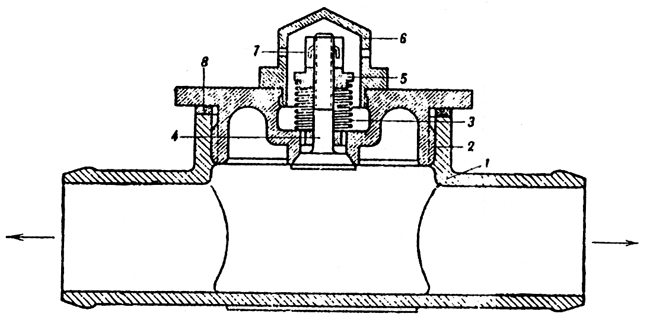 ��
n�gJ{az
��
n�gJ{az Plate 21 - Filler T-piece with air valve
e34g=]"��� 1. T-piece
�7Ou]!AOhG 2. Body of air valve
�:RDk{^b) 3. Spring
d"� 0&=�/� 4. Valve
t�(����vyi 5. Nut
�bz 7?F!� 6. Cap
-`\n/"#X6i 7. Split pin
�1}Guhayy� 8. Packing
�;y��7+��Q 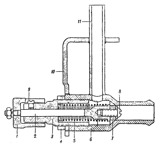 s�(Wy�s^[g
 Plate 22 - Steam Valve
3�QXs�r<�� 1. Nut
"P��S ) "t 2. Valve spindle
�zXUB6.
e� 3. Adjusting nut
}s"]�.Xm^2 4. Chock nut
�9W-�"�mD; 5. Spring
&*�8.%�qe; 6. Body of valve
*Cp:�<M�nd 7. Rubber valve
?N9Z;�_&^. 8. and 9. Screws
D������D�� 10. Bracket
7'8G�,|&:* 11. Steam escape pipe
'xG{q+jj�' The steam valve (Plate 22) is fitted to the upper half of the engine Compartment bulkhead. The body of the valve is connected to the steam escape pipe of the right radiator. The steam outlet pipe (#11) of the valve leads outside through a hole in the hull of the tank.
FQ�0 ;��%Z The nut (#1) of the valve serves as a control and is situated inside the fighting compartment.
./zzuKO8XK The steam valve is adjusted to open at pressures of 0.6-0.8 atmospheres above atmospheric pressure, thereby safe-guarding the radiators from internal pressure.
�6*�EIhIQ( When filling up and draining off water, it in necessary to turn the nut (#1) to the right or left so that the cooling system is connected to the atmosphere. When filling up or draining off is finished. the steam valve must be closed again by screwing up the nut.
;�F���u�ST Starting up the engine by compressed air The compressed air system is an alternative method of starting the engine and is used when the electric starter will not work.
*6]�[�[�)( CONSTRUCTION AND ACTION OF COMPRESSED AIR STARTING SYSTEM @+
T33X)h% The system of starting the engine by compressed air (Plate 23) consists of two compressed air bottles, a reduction valve (#8), pressure gauge (#9), air distributor to cylinders (#12) (mounted on the engine), pipes (#13) from the air distributor to cylinders and twelve outlet valves (one for each cylinder).
9Y�:.v@:}0 The compressed air bottles are fitted on special brackets (#2) in the nose of the tank.
Myn51pcz�l The capacity of each bottle is 10 litres and the maximum pressure in the bottle is 150 atmospheres. Each bottle has a valve by means of which it is connected to the control system. Air from the bottles travels through the pipe (#4) to the T-piece (#5) and to the reduction valve.
Gh6�U<;V?* The T-piece is designed for refilling the bottles with air without removing them from the vehicle.
a"�.�iVf6y The reduction valve (#8) is designed for adjusting the air pressure at the air distributor of the engine. It is mounted at the left of the driver.
.i ���)n�1 The pressure gauge which reads up to 250 atmospheres indicates the pressure in the bottles (when the valves are opened). Procedure for starting the engine by compressed air is described in Chapter VII - Maintenance.
Mcz;`h|E�W 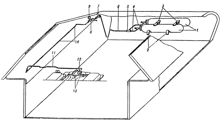 ZmkH55Cn��
 Plate 23 - Layout of Compressed Air Starting System
t@ri`�?�0w 1. Compressed air bottles
�Piw i��� 2. Brackets
(i\�{hq/� 3. Clamps
1Ke�9H!�_P 4. Pipes
ru/{s�3��� 5. T-piece
`|&0�j4(Pg 6. Pipe Connecting T-piece
[_ �uT�+q3 7. T-piece for filling air bottles
,y-��!h@( 8. Reduction valve
z�[vu-�f9� 9. Pressure gauge
�hAds15 %C 10. Pipe
'�
Q�lj"U� 11. Transverse pipe
M17+F?27�M 12. Air distributor
x1Z'_�Qw 13. Pipes connecting air distributor to cylinders.
'ahZ*@�k�r Care of the Compressed Air Starting System s^.tj41Gx} It is necessary to test the air pressure in the bottles periodically during inspection of the vehicle.
?�M�fwRW�Y The pressures in the bottles must not be lower than 40 atmospheres in the summer and not lower than 60 atmospheres in the winter. The pressures should be increased in the case of a worn engine. If the pressure is lower than instructed, starting will be made more difficult.
�hW�~�UJ/$ INSTRUMENT PANEL >Xij+tt�{ The instrument panel carries the following instruments :
OaT��]2�o 1. Two pressure gauges of which one indicates the fuel pressure and the other the oil pressure.
��OXl0�R{4 2. Three aero-thermometers of which one indicates the temperature of the oil entering the engine, one the temperature of the oil leaving the engine and the third the temperature of the water leaving the engine .
�A|4
3W��= 3. Tachometer showing the revs of the crankshaft.
X>pCk�G��E 4. Clock. A speedometer is mounted on the suspension casing of the left front bogie wheel.
��^R
:zm�a C]3�:&d�x9 Chapter III. TRANSMISSION
 BaUuDo�/ZO
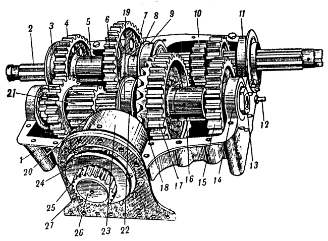
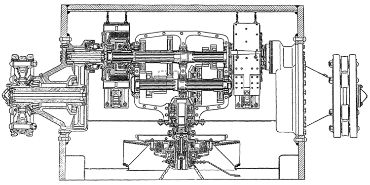
 Plate 24 - Transmission of the tank
=j20A6gND ENGINE CLUTCH �N�YKYj`K� The engine clutch is multiplate, dry with steel friction plates. It consists of driving and driven parts and a withdrawal mechanism. The operation of the clutch from the driving compartment is carried out by means of a linkage (Plate 26).
q-@&n6PEOZ 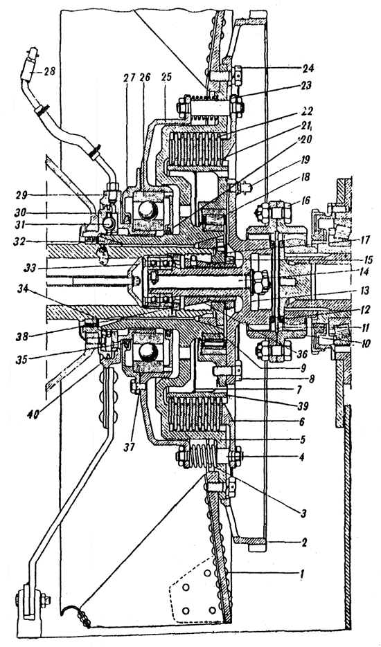 ��u��] G�
 Plate 25 - Engine Clutch
6w�bH{}\ll 1. Fan
BW�3Q03SW6 2. Starter ring
m��$hk�mD| 3. Spring
!?��J-��Y� 4. Stud
��S !lrn�H 5. Flywheel
Cha�d}zU`� 6. Pressure plate
��RFS�wX*! 7. Oil excluder plate
4MzPm�~Ct� 8. Bolt
9�p�r��.`w 9. Cone
+~P_o�_�M� 10. Coupling
j0Cj&x%qF} 11. Ring
/<-=1XJI� 12. Packing
Br�d9"�M|d 13. Hub
�Ek_<2�!%X 14. Scouring bolt
z�TPNQ0�=| 15. Nut
�=�w:)�AWZ 16. Fitted bolts
C CLc,r�>) 17. Plug
��@A`j Wao 18. Roller bearing
O�T�Ae#]�# 19. Lubricator
b�Va?�yWb. 20. Gland
Eg}�U.ss�^ 21. Driven plate
Nq6;z�)$ 22. Driving plate
OZz!8-|w�E 23. Lock washer
�K�W
�ZEi? 24. Bolt
cf�^��i!X0 25. Disengaging plate
�Wl�+spWqW 26. Ball bearing
YRv�96�|c, 27. Cover
$��-j�j%kS 28. Lubricator
�
M_%c9g@x 29. Control box
���M0�?%r` 30. Fixed face cam
O'@��[�f{ 31. Ball of withdraw mechanism
0S�&J=�2D! 32. Cone
_7��qa~7?f 33. Ball bearing
�O.\\)8�xA 34. Packing
>lyE@S sA 35. Gland
Jf#-O�l�EQ 36. Conical plug
19���[!9ci 37. Packing
}J-e:FUF# 38. Nut
�_��I3�v"d 39. Driven drum
�8^_e>q*W 40. Cast iron ring
*�(5T?p�[7 The driving plate of the clutch comprises of (Plate 25): flywheel (#5), disengaging plate (#25), pressure plate (#6) and ten steel driving plates (#22). The flywheel is seated on splines of the crankshaft, it is centered on it by two bronze cones (#9) and (#32) secured by a plug (#17) which is located by the cone (#36) tightened by the nut (#15) screwed on to its stem.
/?b�{*<TK To safeguard against the cone moving and tightening the nut (#15), there is a dowel that fits into one of the slits of the plug (#17).
�<5#2^���( The internal surface of the flywheel is splined to mesh with the teeth of the driving plate (#22). Around the flywheel plate are positioned sixteen holes for the studs (#4). The fan (#1) is fitted to the flywheel plate on the side of the engine and on the side of the gearbox a toothed ring for the starter.
G;[O~N3�n. The fan is secured by 27 bolts, of which 24 are used to secure the toothed starter ring.
*XYp��~b�� The disengaging plate (#25) and the pressure plate (#6) have sixteen holes. These plates (#25) and (#6) are joined to each other by the studs (#4) and are secured by nuts. The springs (#3) pressing against the friction plates are carried on the studs between the flywheel and disengaging plate. Between the shoulders of the studs (#4) and the pressure plate two washers (#13), 0.5 mm. are fitted. These washers are designed for the normal maintenance adjustment of the clutch.
;�n|%W�,b- The driving plates (#22) are made of steel; their outer circumferences are splined and are in mesh with the teeth of the flywheel. Thus all the driving components of the engine clutch rotate in one piece with the crankshaft.
?1O`
Rd{tn The driven parts of the clutch comprise of: The driven drum (#39), with hub (#13) and twelve steel driven plates (#21).
w8��:���� The outer surface of the driven drum is splined and in mesh with the teeth of the driven plates. On the outside, the driven drum is connected to the hub, (the end of which is splined), by means of eight bolts.
o�SjY�p(h: The driven drum runs on a ball bearing (#18) seated on the hub of the flywheel. (In tanks of the first model the driven drum had two supports; a roller bearing on the hub of the flywheel and two ball bearings in the end of the crankshaft, through the tail piece of its hub, the driven drum rested on these bearings.
���Z.x]6�� The connection between the driven drum and the driving shaft of the gearbox is in the form of a geared tooth coupling (#10). One half of the coupling meshes with the tooth of the hub (#13) and the other half with the gear of the driving shaft. Both: halves of the coupling are connected to one another by fitted bolts (#16).
\Md�i��eO* The driven plates have teeth, the inside of which mesh with the toothed driven drum. All the driven plates of the engine clutch rotate in one piece with the driving shaft of the gearbox.
4�pelI�o�j Withdrawal mechanism of the engine clutch comprises of:
9��%"\�s2T # fixed face cam (#30)
][#|�5UK8L # separator with three balls (#31)
>�vY�b'%02 # control box (#29).
|Q�R9#�I�v The fixed face cam is bolted and doweled to the crankcase.
�H;q[$EUNb The control box is a press fit in the inner race of the ball bearing (#26) the outer race of which, is housed in a seating of the cover of the disengaging plate provided with felt ring oil seals. To the control box a grooved ring of special shape is fitted for balls. In the fixed face cam there are also grooves of the same shape on the other half of the face cam.
1�;B&R�89} Between the fixed face cam and the control box there is a separator with balls which run in the grooves.
;�R<�V-gab Note. In T-34 tanks with M-17 engine, the engine clutch is the BT type.
( *K)�D$y� 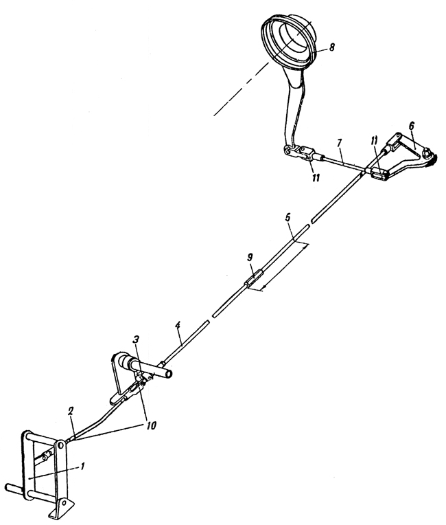 Bu?Qy�z2�O
 Plate 26 - Engine Clutch Control Linkage
B&1E�&Cv_8 1. Pedal
to1r
8�8X� 2. Inclined rod
8A:�:�q�; 3. Supporting lever
s%>8y\MaK� 4. Front part of long tie-rod
L`w�r~E2u� 5. Rear part of long tie-rod
�\����!w | 6. Double arm lever
q"�S,<�I<f 7. Transverse lever
L8Z�@Dk�7Y 8. Control box
�qzO5p=}� 9. Adjustment
9�`"#OQPn1 10 & 11. Feed joints
�Y�" rODk1 Adjustment of the clutch. A. To adjust the clearance in the balls of the withdrawal mechanism to within 0.9 -1.1 mm. 1. Unscrew the nuts securing the spring loaded studs (#4). 2. Remove the pressure plate. 3. Remove one adjusting washer from each stud. 4. Replace pressure plate.
W�IAukM8~� If the travel of the tie-rod measures from 20 - 25 mm then the clearance in the balls of the withdrawal mechanism will be from 0.9 -1.1 mm.
5�DkEJk7a� B. To adjust the travel of the pressure plate to 6 to 7 mm. 1. Adjust the fork (#10) on the inclined tie-rod. 2. Alter the adjusting nut (#9) on the long tie-rod.
PRFl%�M.H` GEAR BOX �BnDCK@+|Q Translator's Note: The gearbox is of normal sliding mesh type of a very usual design with four speeds forward and one reverse and it has not been considered necessary to make a full translation of its description.
)iK:BL�*Nw The gearbox casting is of aluminium and made in two halves. Recently it has been made of cast iron.
BJ'pe[�Xa5 It is operated by a selector mechanism (Plate 30) on the right of the driver to which is fitted a lock to prevent reverse gear being accidentally engaged when moving forward.
[f[Wz�{Q#Y